9
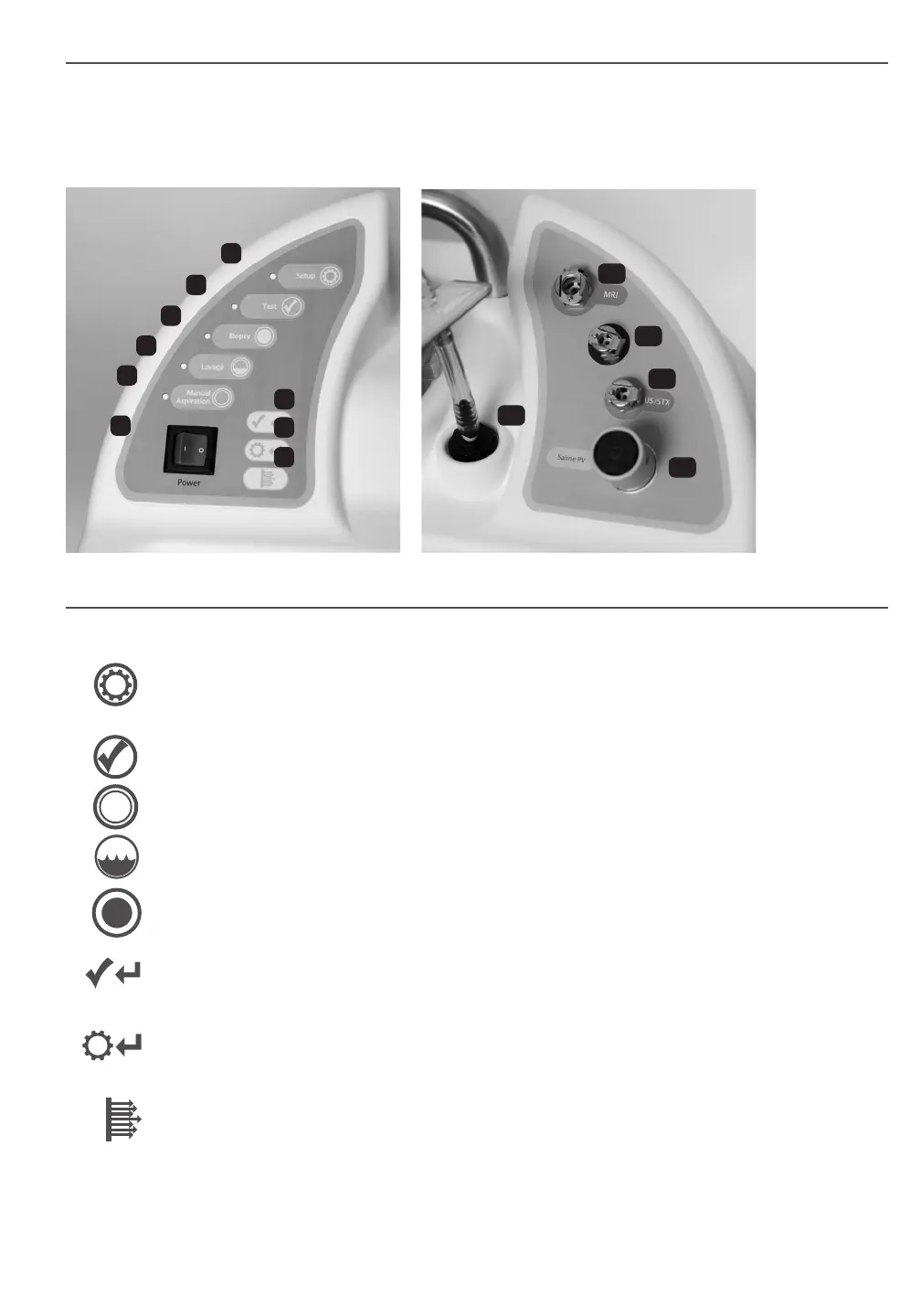
Console Controls and Functions
The console user interface panels include controls that enable the user to operate the ATEC system and indicator lights that
provide additional information about system status. A detailed description of each component on the user interface can be
found below.
LEFT USER INTERFACE RIGHT USER INTERFACE
Console User Interface
1. Power Switch - Turns power to the console on and off: On = Illuminated green and “ I ”
Off = Not Illuminated and “ O ”
2. “Setup” Button - This push button control allows for the self-priming of the system with saline. When placed in
“Setup” mode, the “Saline PV” (Pinch Valve) is opened and the vacuum is turned on, allowing insertion of the
silicone tubing section of the handpiece saline line.
3. “Test” Button - This push button control activates the handpiece through one test cycle. The system will return
to “Biopsy” mode upon successful completion of one test cycle.
4. “Biopsy” Button - When placed in “Biopsy” mode, the handpiece is ready for tissue acquisition. Footswitch
input begins biopsy cycling.
5. “Lavage” Button - When placed in “Lavage” mode, the “Saline PV” is opened and vacuum is turned on to
irrigate and aspirate the biopsy cavity.
6. “Manual Aspiration” Button - When placed in “Manual Aspiration” mode, the “Saline PV” is closed and
the inner cutting cannula is retracted. In this mode, the user can vacuum the biopsy cavity by depressing the
footswitch.
7. “Retest Handpiece” Indicator - Does not illuminate under normal conditions. Flashes red when “Test” or
“Biopsy” mode is not completed due to pressure failure. Refer to the Troubleshooting section for suggested
steps to diagnose and correct a potential problem.
8. “Return to Setup” Indicator - Does not illuminate under normal conditions. Flashes red when “Test” mode is
not completed due to vacuum failure. Refer to the Troubleshooting section for suggested steps to diagnose and
correct a potential problem.
9. “Vacuum Ready” Indicator - Illuminates solid green when the console has achieved full vacuum. Flashes
green when full vacuum is not achieved within the specied timeframe. If this indicator ashes, refer to the
Troubleshooting section for suggested steps to diagnose and correct a potential problem. The footswitch will not
enable the handpiece to function unless this indicator is illuminated solid green.
10. Vacuum Line Assembly - This is clear tubing that is permanently attached to the console at one end. The other end
has a blue connector that will attach to the Suction Canister lid at the port labeled “VACUUM”.
1
7
8
9
10
11
12
13
14
5
6
4
3
2