12
FEATURES
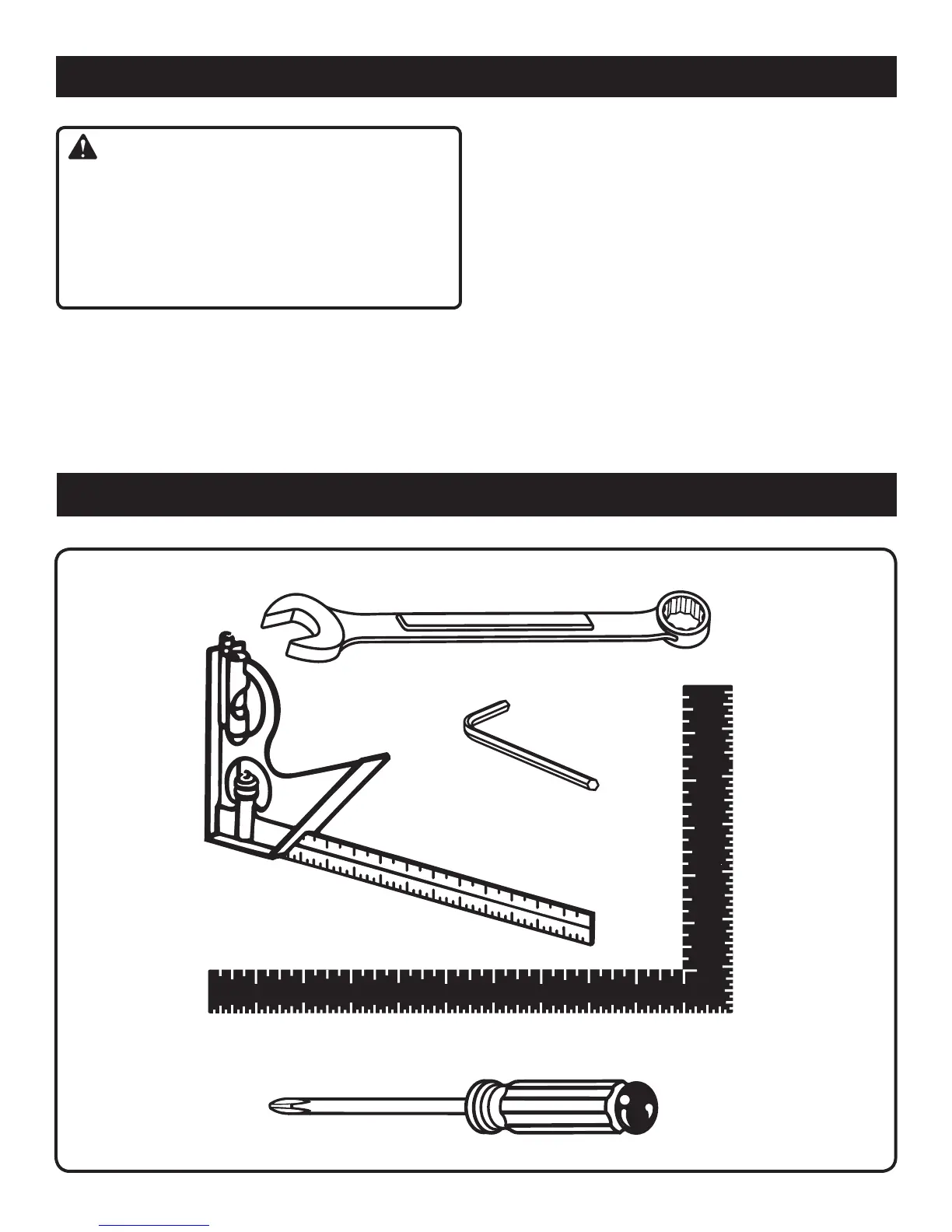
The following tools (not included) are needed for making adjustments or installing the blade:
TOOLS NEEDED
Fig. 5
COMBINATION SQUARE
FRAMING SQUARE
COMBINA
TION WRENCH (2)
10 mm, 14 mm
HEX KEY
5 mm
PHILLIPS SCREWDRIVER
ELECTRIC BRAKE
An electric brake has been provided to quickly stop blade
rotation after the switch is released.
FENCE
The fence on your compound miter saw has been provided
as a support to hold your workpiece securely against when
making all cuts.
SELF-RETRACTING LOWER BLADE GUARD
The lower blade guard is made of shock-resistant, see-
through plastic that provides protection from each side of
the blade. It retracts over the upper blade guard as the saw
is lowered into the workpiece.
WARNING:
The operation of any saw can result in foreign objects
being thrown into your eyes, which can result in severe
eye damage. Before starting power tool operation, always
wear safety goggles or safety glasses with side shields
and a full face shield when needed. We recommend wide
vision safety mask for use over eyeglasses or standard
safety glasses with side shields.
BEVEL LOCK KNOB
The bevel lock knob securely locks your compound miter
saw at desired bevel angles. A positive stop adjustment
screw has been provided on each side of the saw arm.
These adjustment screws are for making fine adjustments
at 0° and 45°.
 Loading...