EasyManua.ls Logo

Honda 08E51-S01-101F User Manual

Honda 08E51-S01-101F
8 pages
To Next Page IconTo Next Page
Page #1 background imageLoading...
Page #1 background image
© 1999 American Honda Motor Co., Inc - All Rights Reserved. AII 20456 (9908) 1 of 8
Security Attachment:
P/N 08E55-S01-100H
LED
Disarm switch
Push nut (for LED)
2-Pin connector
INSTALLATION
INSTRUCTIONS
08E55-S01-1H00-91
Accessory Application Publications No.
Issue Date
PARTS LIST
Security System:
P/N 08E51-S01-101F
SECURITY SYSTEM
Remote Transmitter:
P/N 08E61-S01-101
(Required for HX model only)
2 Transmitters
AUG 1999
2000 CIVIC
2-DOOR
(HX/EX/Si MODELS ONLY)
Owner’s Manual
(discard)
2 Washer-screws
(not used)
Relay 4-pin
Relay 5-pin
2 Fuses (3A)
2 Long wire ties
Card
(not used)
2 Decals
Fuse box label
Control unit
Owner’s Manual
AII 20456
Control unit bracket
Y0540-B
Question and Answer IconNeed help?

Do you have a question about the Honda 08E51-S01-101F and is the answer not in the manual?

Honda 08E51-S01-101F Specifications

General IconGeneral
BrandHonda
Model08E51-S01-101F
CategoryCar Alarm
LanguageEnglish

Summary

Installation Procedure

Initial Setup and Preparations

Prepare the vehicle and system by noting codes, disconnecting the battery, and verifying control unit settings.

Interior Panel Removal

Remove driver's dashboard lower cover, knee bolster, left kick panel, and upper steering column covers.

Install LED and Disarm Switch Components

Install the LED by drilling a hole and securing it, then prepare for the disarm switch installation.

Connect Disarm Switch and Mount Control Unit

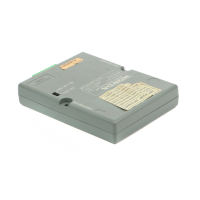
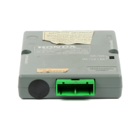
Route disarm switch harness, connect its terminals, and mount the control unit bracket and control unit.

Secure Control Unit and Fuse Box Modifications

Secure the control unit, connect the main harness, and modify the fuse box with new fuses and label.

Connect Relays and LED Harness

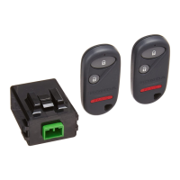
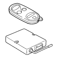
Connect 4-pin and 6-pin relays, and connect the LED harness with the resistor to the vehicle harness.

Final Connections and Inspection

Connect Disarm Switch Harness

Route and secure the disarm switch 3-pin connector to the vehicle harness using cushion tape and a wire tie.

System Inspection and Final Checks

Verify all connections, reinstall parts, reconnect battery, check system operation, and store manuals.

Related product manuals