EasyManua.ls Logo

Honda P/N 08E51-S01-101F User Manual

Honda P/N 08E51-S01-101F
10 pages
To Next Page IconTo Next Page
Page #1 background imageLoading...
Page #1 background image
© 1999 American Honda Motor Co., Inc - All Rights Reserved. AII 20447 (9908) 1 of 10
INSTALLATION
INSTRUCTIONS
08E55-S01-1010-91
Accessory Application Publications No.
Issue Date
PARTS LIST
Security System (sold separately):
P/N 08E51-S01-101F
SECURITY SYSTEM
Security Harness (sold separately):
P/N 08E55-S01-101
AUG 1999
2000 CIVIC
2/3/4-DOOR
(DX/CX MODELS ONLY)
Owner’s Manual
(discard)
2 Washer-screws
(not used)
Relay 4-pin
Relay 5-pin
2 Fuses (3A)
(not used)
2 Long wire ties
(not used)
Card
(not used)
2 Decals
Fuse box cover
(not used)
Control unit
Security harness
5 Wire ties
AII 20447
Cushion tape
Fuse label
Y0540-B
Question and Answer IconNeed help?

Do you have a question about the Honda P/N 08E51-S01-101F and is the answer not in the manual?

Honda P/N 08E51-S01-101F Specifications

General IconGeneral
BrandHonda
ModelP/N 08E51-S01-101F
CategoryCar Alarm
LanguageEnglish

Summary

Installation Preparation and Initial Steps

Customer Information and Manual Notes

Provides technician guidance and notes on owner's manuals for the security system.

Battery Disconnection and Control Unit Setup

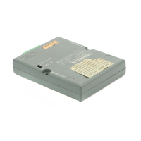
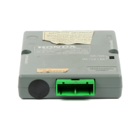
Covers disconnecting the battery and setting the control unit switch for specific models.

Dashboard and Knee Bolster Removal

Details the procedures for removing the driver's dashboard lower cover and knee bolster.

Panel Removal and LED Installation

LED Mounting and Wiring

Details drilling a hole and mounting the LED on the steering column cover.

LED and Disarm Switch Integration

LED Connector Integration

Connects the LED terminals into the 2-pin connector.

Disarm Switch Mounting

Procedure for drilling and mounting the disarm switch on the dashboard lower cover.

Disarm Switch Connector Integration

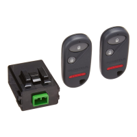
Connects the disarm switch terminals into the 3-pin connector.

Control Unit Installation

Control Bracket Mounting

Loosens a bolt and slides the control bracket onto the steering shaft.

Harness Connections - Part 1

Harness Connections - Part 2

Final Harness Connections and Cover Reinstallation

Final Connections, Inspection, and Documentation

Final Inspection and System Check

Checks wiring, connectors, and verifies system operation as per the owner's manual.

Related product manuals