EasyManua.ls Logo

Honda Odyssey 1999 User Manual

Honda Odyssey 1999
12 pages
To Next Page IconTo Next Page
Page #1 background imageLoading...
Page #1 background image
© 1998 American Honda Motor Co., Inc - All Rights Reserved. AII 19610 (9810) 1 of 12
INSTALLATION
INSTRUCTIONS
08E55-S0X-1F01-91
Accessory Application Publications No.
Issue Date
OCT 1998
1999 ODYSSEY (EX)ALARM SYSTEM
PARTS LIST Alarm Attachment Kit:
P/N 08E55-S0X-100F
Control unit bracket
Sub-harness
12 Wire ties
4-Pin relay
LED
Push nut
2-Pin connector
Disarm switch
Window label
3-Pin connector
Nut, 12 mm
Washer
Owner’s Manual
2 Washer-screws, 4 x 30 mm
Ground bolt
Alarm harness
Wire tie with clip
Relay bracket
Washer-bolt, 6 x 12 mm
All 19610
Y0505-D
Flange nut
Fuse labels
Control unit
Alarm System:
P/N 08E51-S0X-100
HandA-Accessories.com
Question and Answer IconNeed help?

Do you have a question about the Honda Odyssey 1999 and is the answer not in the manual?

Honda Odyssey 1999 Specifications

General IconGeneral
ManufacturerHonda
ModelOdyssey
Year1999
CategoryCar Alarm
Alarm SystemFactory-installed security system

Summary

Parts List

Adjusting the Control Unit

Mode Switch

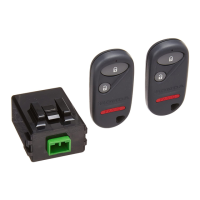
Sets the mode switch per customer choice. Refer to Owner's Manual for mode explanations.

Glass Breakage Sensor

Do not cover sensor holes; they are for the microphone pickup.

Sensitivity Adjustment Knob

Adjust sensitivity only upon customer request. Avoid false alarms by setting sensitivity carefully.

Tools and Supplies Required

Installation Procedure

Initial Preparation Steps

Includes writing frequencies, disconnecting the battery, and removing the fuel lid opener.

Trim and Cover Removal

Covers removal of door sill trim, kick panel, and steering column covers.

Console and Radio Removal

Details on removing the center console panel and the vehicle radio.

Routing the Alarm System Wire Harness

Fuse Box Connections

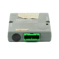
Connecting alarm harness connectors to the vehicle harness at the fuse box.

Ground Wire Installation

Attaching the alarm harness ground wire to the vehicle body using a new ground bolt.

Relay and Control Unit Mounting

Mounting the relay bracket and control unit bracket under the dash.

LED and Disarm Switch Installation

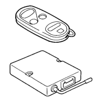
Drilling holes and installing the LED indicator and disarm switch.

Sub-harness Routing

Routing the sub-harness through the glove box area and center console.

Final Steps and Checks

Harness and Connector Securing

Securing the alarm harness and pushing connectors into their final mounting holes.

Reassembly and Testing

Reinstalling parts, reconnecting battery, and checking alarm operation.
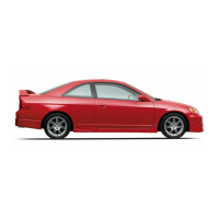
Related product manuals