Do you have a question about the Honda 08L02-SZA-110A and is the answer not in the manual?
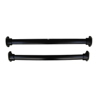
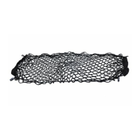
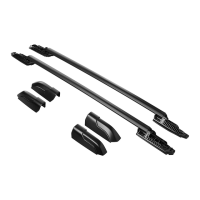
Lists all components required for the roof rail installation, including rails, covers, nuts, and clips.
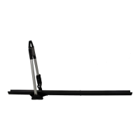
Details necessary tools such as screwdrivers, drill bits, pliers, and safety equipment for the installation.
Involves piercing and drilling holes in the left roof molding cover at specific marks.
Cutting the left roof molding cover with an air saw and lifting the molding off clips.
Removing clips, discarding them, and cleaning excess sealant from stud bolts.
Cutting the roof molding at specified measurements using an air saw.
Attaching new clips, reinstalling roof moldings, and fitting the left roof molding cover.
Securing the left roof rail using Torx nuts and torquing them to specification.
Installing the left front and rear roof rail covers onto the left roof rail.
Repeating the cover installation process for the right side of the vehicle.
Completing the installation by repeating all steps for the right side of the vehicle.
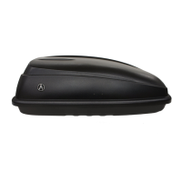
This document outlines the installation procedure for roof rails on a 2015 Honda Pilot, providing detailed instructions for technicians to ensure proper and safe attachment. The primary function of these roof rails is to provide a secure mounting point for carrying additional cargo on the vehicle's roof, thereby expanding its carrying capacity beyond the interior.
The installation process is comprehensive, beginning with preparatory steps that involve careful manipulation of existing vehicle components. Technicians are advised to open the tailgate and use a plastic trim tool to gently pry up the rear end of the left roof molding cover. This initial step emphasizes the need for precision to avoid damaging the vehicle's finished surfaces. Once the molding cover is accessed, the next critical step involves marking and drilling holes. Using a pushpin, two holes are pierced at specific scribe marks on the left roof molding cover. This is followed by drilling these marked locations with a 3 mm drill bit, and subsequently enlarging them to 10 mm. The use of eye protection, such as a face shield or safety goggles, is mandatory during all drilling operations to protect against debris. Any burrs created during drilling must be carefully removed to ensure a smooth and clean surface for subsequent steps.
A significant part of the installation involves modifying the existing roof molding. Technicians are instructed to use an air saw to cut the left roof molding cover along a designated scribe line, again emphasizing the need for eye protection and the removal of any burrs. This modification is crucial for accommodating the new roof rail components. After cutting, the left roof molding is carefully lifted upward from four vehicle roof molding clips, which are then removed and discarded along with any stud bolts. Excess sealant from the stud bolts must also be removed to prepare the mounting surfaces. The roof molding itself is further modified by cutting it at specific measurements using an air saw, ensuring precise fitment for the new roof rails.
Once the modifications to the roof molding are complete, new roof molding clips are installed onto each roof molding. These new clips are essential for securely reattaching the modified roof moldings back into the left roof channel. The reinstallation of the roof molding left cover follows, ensuring that all components are properly aligned.
The core of the installation involves mounting the left roof rail. This is achieved by securing it with four Torx nuts. Technicians are explicitly instructed to ensure the roof rail is installed in the correct position and to torque the Torx nuts to a precise specification of 12 N·m (9 lbf·ft). This torque specification is critical for the structural integrity and safety of the installed roof rail, preventing it from loosening during vehicle operation. After the main roof rail is secured, the left front roof rail cover and the left rear roof rail cover are installed onto the left roof rail, using two clips for each cover. These covers not only provide an aesthetic finish but also protect the mounting hardware from environmental elements.
A key feature of the installation process is its symmetrical nature. After completing all steps for the left side of the vehicle, the entire sequence, from steps 1 through 13, is repeated for the right side. This ensures that both roof rails are installed identically and securely, maintaining the vehicle's balance and structural integrity. The final step involves installing the right roof rail covers in the same manner as the left, completing the aesthetic and protective aspects of the installation.
Regarding usage features, the roof rails are designed to support additional cargo, but there is a crucial limitation: the weight of the cargo must not exceed the maximum weight capacity of 75 kg (165 lbs). This weight limit is a critical safety parameter that users must adhere to to prevent damage to the vehicle or potential hazards during driving. The installation instructions also highlight the importance of being extremely careful not to damage the roof and other finished surfaces of the body when installing the roof rails, underscoring the need for a delicate and precise approach during the entire process.
Maintenance features are not explicitly detailed for the roof rails themselves within this document, as the focus is solely on installation. However, the meticulous nature of the installation, including the removal of burrs and proper torquing of nuts, implies that a correctly installed roof rail should require minimal direct maintenance beyond periodic checks for tightness and general wear. The use of durable materials and precise fitment, as guided by the instructions, contributes to the longevity and reliability of the accessory. The covers installed over the mounting hardware also serve a protective role, shielding critical components from weather and road debris, which indirectly contributes to reduced maintenance needs over time.
The document also includes important disclaimers regarding who should perform the installation. It explicitly states that the information is intended for use only by skilled technicians who possess the proper tools, equipment, and training. "Do-it-yourselfers" are strongly advised against attempting these procedures. This emphasizes the complexity and precision required for the installation, as well as the potential safety risks associated with improper installation. The availability of specialized tools through the Honda Tool and Equipment Program further reinforces the professional nature of this installation. Tools such as the air saw and plastic trim tool are specified, indicating that standard household tools may not suffice for a proper installation.
In summary, these roof rails enhance the utility of the 2015 Honda Pilot by providing a robust and secure platform for external cargo. Their installation is a multi-step process requiring specialized tools, precise measurements, and careful execution by trained professionals to ensure safety, structural integrity, and aesthetic appeal. Adherence to the specified weight limit is paramount for safe operation, and while direct maintenance instructions are not provided, the quality of installation is designed to ensure long-term reliability.
| Color | Black |
|---|---|
| Part Number | 08L02-SZA-110A |
| Category | Automobile Accessories |
| Manufacturer | Honda |
| Compatibility | Honda vehicles |