IV.
FRAME
8. Remove tltc
level'
boot and disconnect the hrakc cable
from the )ever.
Pull the cable toward the caliper
to
re-
move
it.
NOTE:
111c
brake cable
can
be
removed from tlte brake arm
at
tlte cable end. This permits single replacement
of
the
cable without removing
the
wheel.
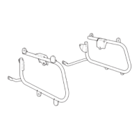
9. Remove the two 6
mm
bolts and a 8 mm boll; dis•
assemble the disc cover, caliper body, caliper joint. and
caliper pin from each other.
Inspection
I.
Check me pads A and B for excessive
or
abnormal wear.
Discard the pad
if
it
is
worn down to the red-line wear
limit
NOTE:
Replace both pads
if
any one pad shows excessi,·e wear
reaching the red-line ljmit.
Assembly
NOTE:
Avoid
oily
or
greasy substances getting on
the
pads
and
disc,
as tltis would affect
the
proper operation
of
the brake.
Wash
them in solvent when oil is soaked.
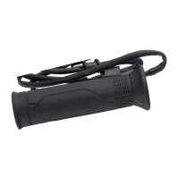
I.
Install the caliper body, caliper pin, disc cover and
caliper
joint
NOTE:
Be
sure to jnstall the caliper pin
in
the
proper
direction.
.i
Fig.
4-18
(l)
Lever boot (2) Brake cable
Fig.
4-19
(1)
Disc
cover (2) Caliper body
(3)
Caliper joint (4) Caliper pin
~
-ij
0.5mm
(0.020in.) ,
(2l· l I
O>
]!
-u
Fig.
4-20
(1)
Pad
A (2)
Pad
8
,
Fig. 4- 21
(I)
Caliper pin
41
 Loading...