32
4. ENGINE
Fig. 87
The valve tappet
adjusting screw is
~ :l-===== not properly
I
contacting the
valve.
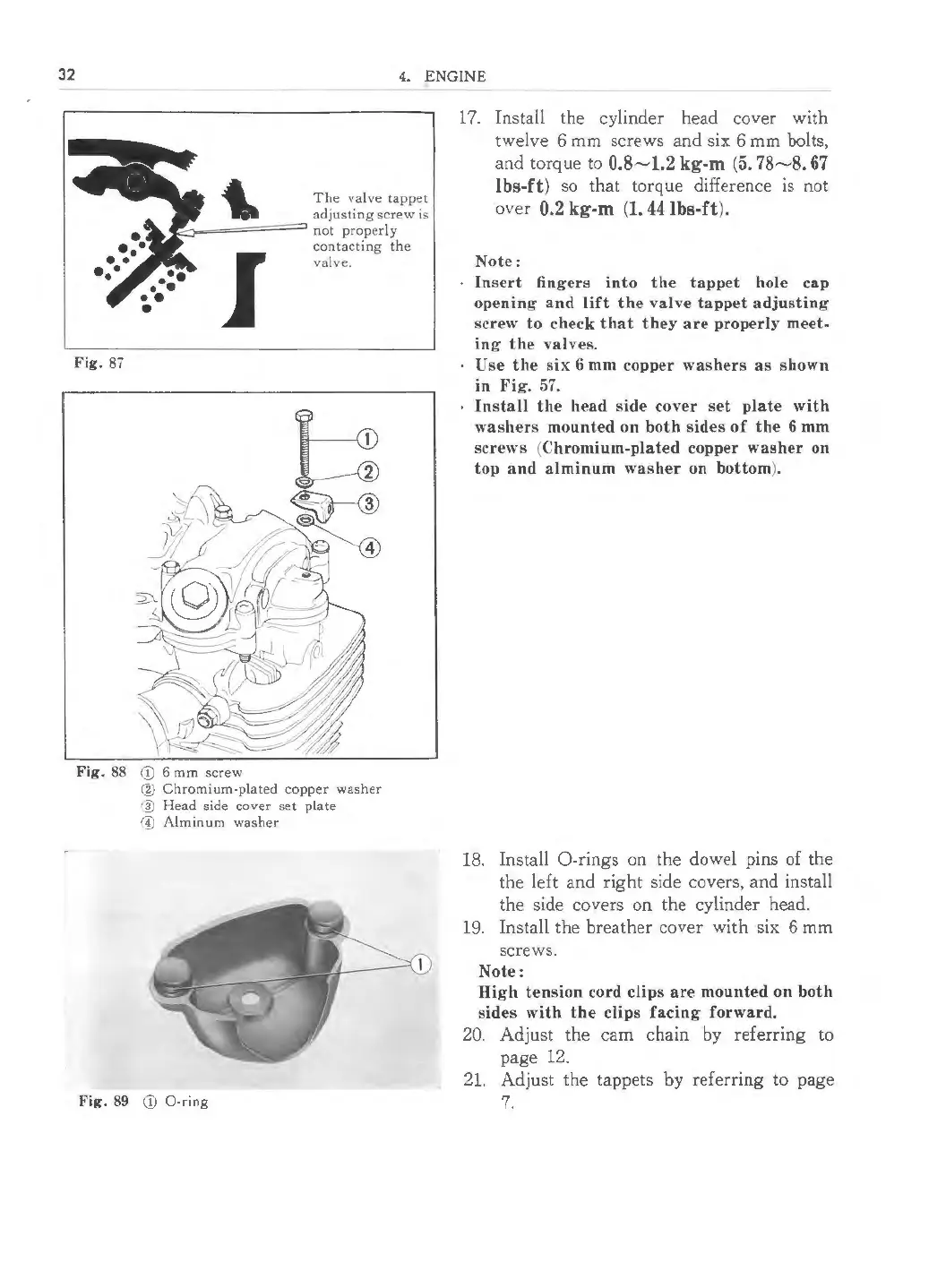
Fig . 88 <D 6 mm screw
® Chromium-plated copper washer
]) Head side cover set plate
© Alminum washer
Fig. 89 (D 0-ring
17. Install the cylinder head cover with
twelve 6 mm screws and six 6 mm bolts,
and torque to
0.8~ 1.2 kg-m (5. 78~ 8. 67
lbs-ft )
so that torque difference is not
over
0.2 kg-m (1. 44 lbs-ft ).
Note:
Insert fingers into the tappet hole cap
opening and lift the valve tappet adjustin g
screw to check that they are properly meet-
ing the valves.
Use the six 6 mm copper washers as shown
in Fig. 57.
Install the head side cover set plate with
washers mounted on both sides of the 6 mm
screws (Chromium-plated copper washer on
top and alminum washer on bottom ).
18. Install 0-rings on the dowel pins of the
the left and right side covers, and install
the side covers on the cylinder head.
19. Install the breather cover with six 6 mm
screws.
Note:
High tension cord clips are mounted on both
side s with the clips facing forward.
20. Adjust the cam chain by referr ing to
page 12.
21. Adjust the tappets by referring to page
7.
 Loading...