6. ELECTRICAL 93
3. CHARGING SYSTEM
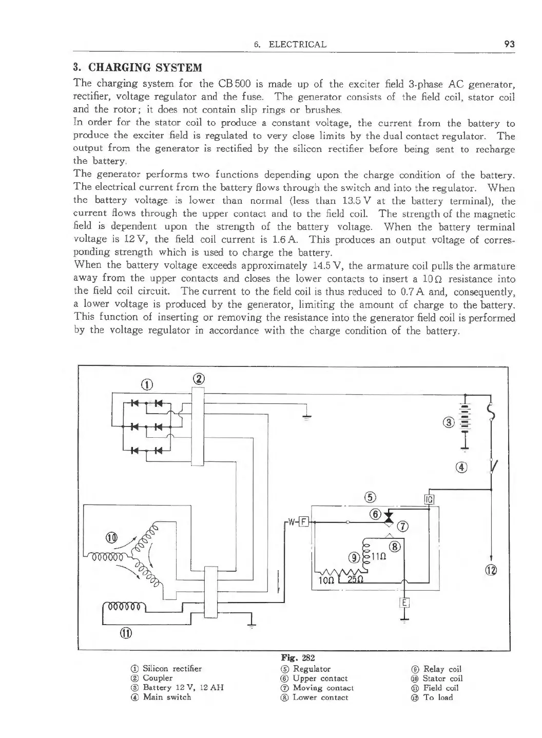
The charging system for the CB 500 is made up of the exciter field 3-phase AC generator,
rectifier, voltage regulator and the fuse. The generator consists of the field coil, stator coil
and the rotor; it does not contain slip rings or brushes.
In order for the stator coil to produce a constant voltage, the current from the battery to
produce the exciter field is regulated to very close limits by the dual contact regulator. The
output from the generator is rectified by the silicon rectifier before being sent to recharge
the battery.
The generator performs two functions depending upon the charge condition of the battery.
The electrical current from the battery flows through the switch and into the regulator. When
the battery voltage is lower than normal (less than 13.5 V at the battery terminal), the
current flows through the upper contact and to the field coil. The strength of the magnetic
field is dependent upon the strength of the battery voltage. When the battery terminal
voltage is 12 V, the field coil current is 1.6 A. This produces an output voltage of corres-
ponding strength which is used to charge the battery.
When the battery voltage exceeds approximately 14.5 V, the armature coil pulls the armature
away from the upper contacts and closes the lower contacts to insert a 10 O resistance into
the field coil circuit. The current to the field coil is thus reduced to 0.7 A and, consequently,
a lower voltage is produced by the generator, limiting the amount of charge to the battery.
This function of inserting or removing the resistance into the generator field coil is performed
by the voltage regulator in accordance with the charge condition of the battery.
CD Silicon rectifier
® Coupler
@ Battery 12 V, 12 AH
© Main switch
@
®
W F 1-++-- --0-- --. (j)
Fig. 282
® Regu lator
® Upper contact
® Moving contact
® Lower contact
-
-
® =
l
©
IG
® Relay coil
@) Stator coil
@ Field coil
@ To load
 Loading...