3
UWP Wiring terminal designations
S
Not used for T3
thermostat.
L/A
- A
Not used for T3 thermostat.
S
O/B Changeover valve
Y
Compressor contactor
(stage 1)
AUX -
W2
Auxiliary heat
(TH3210U only)
Y2
Not used for T3
thermostat.
E
Emergency heat
(TH3210U only)
G
Fan W Heat (stage 1)
C
24VAC common. For 2
transformer systems,
use common wire from
cooling transformer.
K Not used for T3 thermostat.
U
Not used for T3
thermostat.
R
24VAC power from heating
transformer*
U
Rc
24VAC power from cooling
transformer*
Note: Not all
terminals may be
used, depending
on the system
type that is being
wired. The most
commonly used
terminals are
shaded.
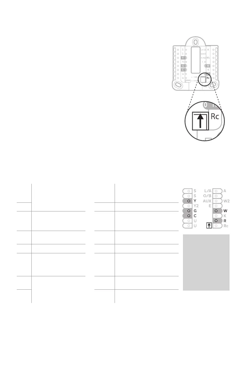
* Terminal can be jumped using Slider Tab. See “Setting Slider Tabs” above.
Set R Slider Tab.
• Use built-in jumper (R Slider Tab)
to differentiate between one or two
transformer systems.
• If there is only one R wire, and it is
connected to the R, Rc, or RH terminal, set
the slider to the up position (1 wire).
• If there is one wire connected to the R
terminal and one wire connected to the Rc
terminal, set the slider to the down position
(2 wires).
NOTE: Slider Tab for U terminals should be left
in place for T3 Pro models.
Setting Slider Tabs (built-in jumper)
R/Rc Slider Tab
(built-in jumper)
UWP Mounting System

 Loading...