Do you have a question about the Honeywell Home T4 Pro Series and is the answer not in the manual?
| Display | Digital |
|---|---|
| Programmable | Yes |
| Wi-Fi | No |
| Backlight | Yes |
| Fan Modes | Auto, On |
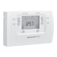
| Model | T4 Pro |
| Power Source | Battery or Hardwired |
| Temperature Range | 40°F to 90°F |
| Terminal Designations | R, C, W, Y, G |
| Operating Modes | Heat, Cool, Off |
| Temperature Range (Cooling) | 50°F to 99°F |
| Programmability | 7-day programmable |
| Stages | 1 Heat/1 Cool |
Lists all items included in the thermostat package for installation and use.
Wiring diagram for single-stage heating systems using gas or oil furnaces.
Wiring diagram for single-stage cooling systems.
Wiring diagram for systems with one stage heat and one stage cool using a gas furnace.
Wiring diagram for systems with one stage heat/cool using a two-transformer oil furnace setup.
Wiring diagram for two-transformer systems with hot water heat and air-conditioning.
Wiring diagram for systems with hot water boilers used only for heating.
Wiring diagram for hot water heat systems using a power-open zone valve.
Wiring for hot water heat systems with Series 20 power-open/closed zone valves.
Wiring diagram for heat pump systems with one stage heat/cool and no auxiliary heat.
Wiring diagram for heat pump systems with two stages heat and one stage cool using electric auxiliary heat.
Instructions on how to set the current time on the thermostat.
Instructions on how to set the current date on the thermostat.
Details on the low battery warning indicator and its meaning.
Configures the thermostat's scheduling capabilities, such as 5-2 or 7-day programming.
Sets the temperature display to either Fahrenheit or Celsius.
Defines the type of heating system the thermostat will control (e.g., forced air, heat pump).
Selects the specific type of heating equipment for optimal control.
Configures the reversing valve operation for heat pumps, specifying energize in heat or cool.
Sets the number of cooling stages or compressor stages controlled by the thermostat.
Sets the number of heating stages and backup heat stages.
Determines if the thermostat or equipment controls the fan during heating.
Enables automatic or manual switching between heating and cooling modes.
Sets the temperature differential for automatic system mode switching.
Adjusts the temperature difference for engaging backup heat.
Configures the delay timer before backup heat engages in heat pump systems.
Limits the number of cycles per hour for the compressor at 50% load.
Limits the number of heating cycles per hour at 50% load.
Sets the cycle rate for auxiliary heat engagement.
Enables a minimum off-timer to protect the compressor from short cycling.
Allows the thermostat to learn system response times for comfort.
Sets the lowest allowable temperature for cooling mode.
Sets the highest allowable temperature for heating mode.
Enables or disables the thermostat keypad lockout feature.
Specifies the number of air filters in the HVAC system.
Sets a reminder for replacing the first air filter based on time or calendar.
Sets a reminder for replacing the second air filter based on time or calendar.
Controls whether the display backlight is on demand or continuous.
Adjusts the brightness level of the thermostat display backlight.
Sets the clock display to either 12-hour or 24-hour format.
Enables or disables automatic adjustment for Daylight Saving Time.
Allows adjusting the displayed temperature relative to the actual room temperature.
Defines the operating and storage temperature limits for the thermostat.
Specifies the acceptable ambient temperature range for thermostat operation.
Indicates the temperature range for shipping and storage.
Defines the acceptable range of non-condensing relative humidity.
Provides the height, width, and depth of the thermostat in inches and millimeters.
Details the voltage and running current specifications for various terminals.
Steps to resolve issues when the thermostat display is not showing anything.
Guidance for when the heating or cooling system fails to start.
Troubleshooting steps for when temperature settings are not affecting the system.
Explanation for the flashing 'Cool On' or 'Heat On' message, usually compressor protection.
Steps to verify wiring issues causing auxiliary heat to run during cooling.
Troubleshooting steps for when cooling activates during a heating call.