20
EN1R--9161 0006R10--NE
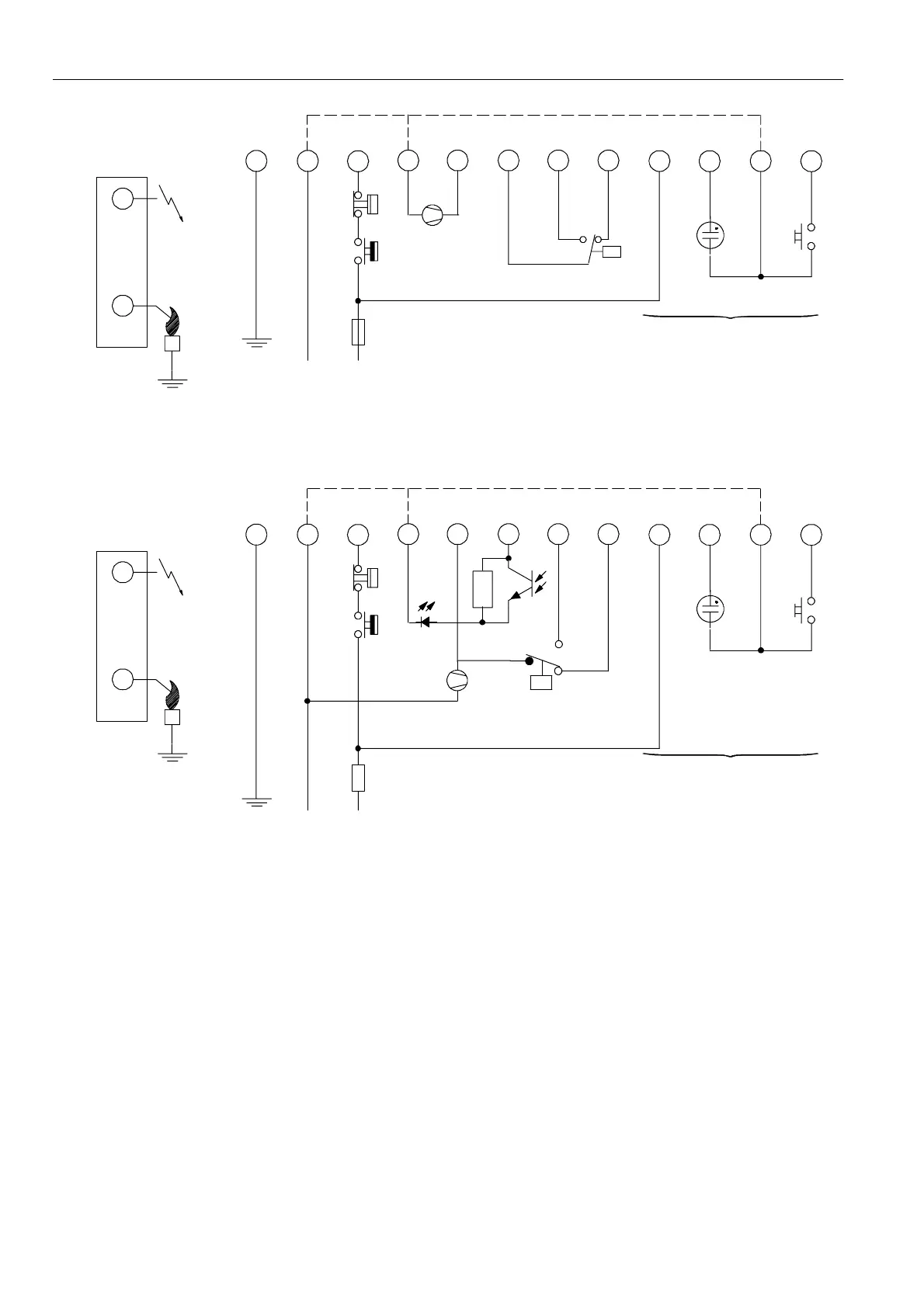
P -- Air proving switch
LM -- Limiter
RS -- Reset switch
* See note 12.
** Alternative side connection for models with combined flame
detection/high voltage. See page 5 fig. 6.
10
3
7
1
L
11
N
Side connections**
8
24
569
LM
P
¯
RS
12
Optional
*
Fig. 35. Connection diagram S4565CF, DF, RF, TF
P -- Air proving switch
LM -- Limiter
RS -- Reset switch
* See note 12.
** Alternative side connection for models with combined flame
detection/high voltage. See page 5 fig. 6.
10
3
7
1
L
11
N
Side connections**
8
24
569
LM
RS
12
Optional
*
CNY 17-- 3
P
22 K
Fig. 36. Connection diagram S4565DF, TF with external main burner interrupt
SYSTEM OPERATION
General
Lock- out reset
The S4565 can be is reset by either depressing the
internal/external reset button (suffix AF, BF, CF and DF) or by
inte rrupting the permanent life (suffix PF, QF, RF, and TF).
NOTE 11.: If during normal use the reset button is pressed,
the gas valves close and the S4565 ignition
control starts a new sequence after releasing the
reset button.
NOTE 12.: If permanent alarm output:
neon indicator with integral resistor >150 kτ
Εmax 1 mA)

 Loading...