EasyManuals Logo

Honeywell 2000 Series User Manual

Honeywell 2000 Series
12 pages
To Next Page IconTo Next Page
To Previous Page IconTo Previous Page
Page #6 background imageLoading...
Page #6 background image
SERIES 2000 ELECTRONIC TEMPERATURE SENSORS
63-2590—05 6
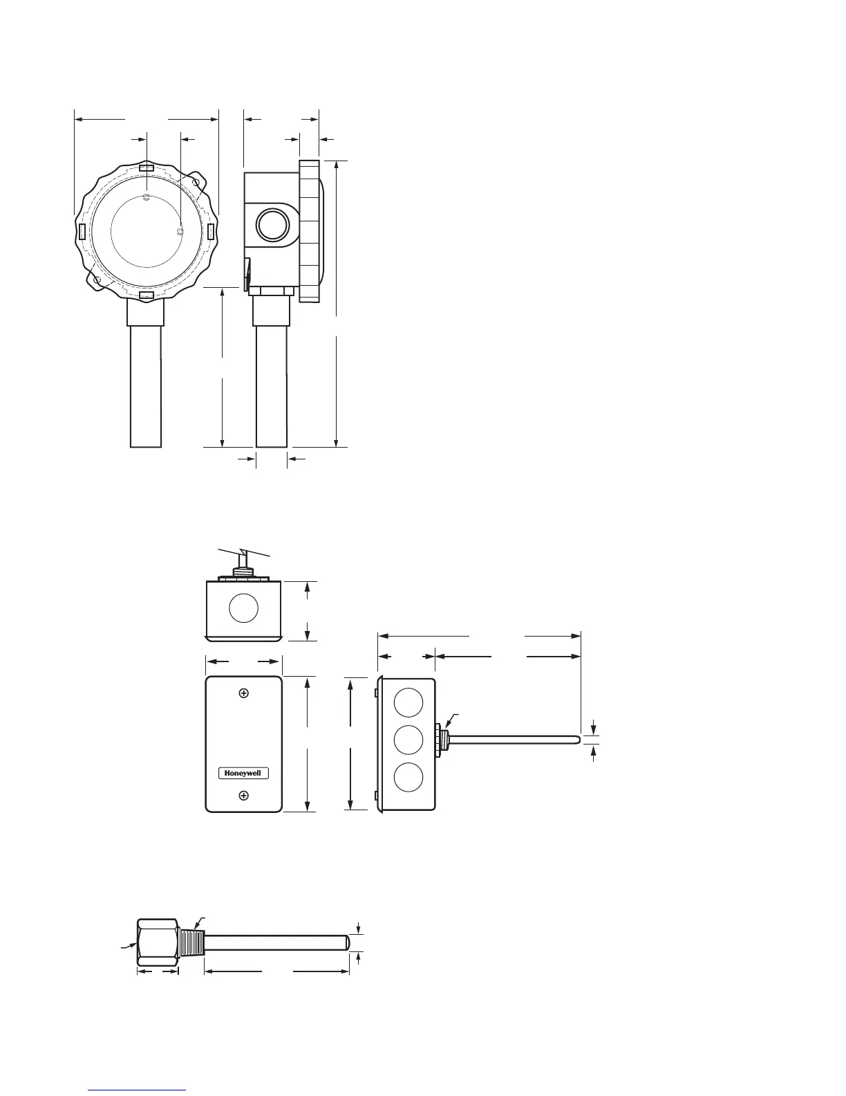
Fig. 4. C7031G, C7021F, C7023F, C7041F dimensions in in.
(mm).
Fig. 5. C7021D, C7023D, C7031D, C7041D dimensions in in. (mm)
NOTE: The C7021D, C7023D, C7041D uses the 50001774-
001 Well Assembly. See Fig. 4 for dimensions.
Fig. 6. 50001774-001 Immersion Well dimensions in in.
(mm)
2-1/4 (57)
3/4
(19)
1 (25)
5
(127)
7/8
(22)
8-5/16
(211)
M22132
3-5/8 (91)
2-5/16
(59)
1-11/16
(43)
4-3/16
(107)
1/4
(6)
4
(70)
1-11/16
(43)
6-11/16 (170)
M22596
5 (127)
1/2 NPSM (13)
3/4
(19)
3/8 (10)
1
(26)
4 (102)
FITS 1/2 NPT TAPPED HOLE
M27052
1/2 NPSM
INTERNALLY
THREADED

Other manuals for Honeywell 2000 Series

Questions and Answers:

Question and Answer IconNeed help?

Do you have a question about the Honeywell 2000 Series and is the answer not in the manual?

Honeywell 2000 Series Specifications

General IconGeneral
Control TypeOn/Off, PID
Input TypeThermocouple, RTD
Output TypeRelay
Supply Voltage24 VAC/VDC, 100-240 VAC
DisplayLED
MountingPanel
CommunicationRS-485 (Optional)
Operating Temperature-10 to 50 °C

Related product manuals