Fig. 10
Cut Wires
8
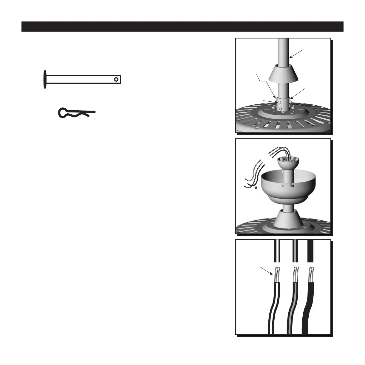
STANDARD OR ANGLE MOUNTING INSTRUCTIONS
9. Slide the downrod into the yoke of the motor
assembly, align the holes, and re-install the
downrod pin and downrod clip. Then re-tighten the
set screws (Fig. 9).
10. Depending on the length of downrod you use, you
may need to cut the lead wires back to simplify the
wiring. If you decide to cut back the lead wires,
it is suggested that you do so in the following
manner: Take the lead wires and make sure that
you have pulled them all the way through the top
of the downrod and measure 8 in. of lead wire, and
then cut the excess wire off with wire cutters (not
included) (Fig. 10).
11. If you cut back the lead wire in Step 10, strip 1/2
in. (12 mm) of insulation from the end of each wire.
Twist the stripped ends of each strand of wire within
the insulation with pliers (not included) (Fig. 11).
Note: If you did not cut back the lead wires in Step 10,
Step 11 is not necessary and you may proceed to
Step 12 instead.
Downrod
Downrod
Pin
Set Screw
Downrod
Clip
Fig. 9
Fig. 11
Stripped
Wires
Downrod Pin
Downrod Clip
 Loading...