HONEYWELL 7000 SOLID STATE ALARM SYSTEM
69-1192—1
14
Four-Wire Smoke Detector Circuit
Loop 8 of the Honeywell 7000 System control panel can
supervise four-wire smoke detectors with the wiring
arrangements shown in Fig. 19. Use the approved equipment
listed in Table 4.
Table 4. Approved four-wire smoke detection devices.
Manufacturer Model
Sentrol 449CT Detector
Detection Systems DS250, DS240TH Detectors;
MB4W, MB4WL Bases
Honeywell EM100 End-of-Line Module
AlarmSaf Relay AS/BRK-624 Reset Relay
Four-Wire Circuit Installation
1. Use 18 AWG FPL cable such as Honeywell
AK4704ARE.
2. Secure the smoke alarm reset relay module in the
bottom of the Honeywell 7000 System metal box as
shown in Fig. 19 with double-sided tape (provided).
3. Install smoke and heat detectors in accordance with
manufacturer instructions.
4. Wire the circuit as shown in Fig. 16.
IMPORTANT
Do not exceed the +13.8V total current draw with all
detectors in alarm.
5. Connect the End-Of-Line Module at the last smoke
detector. All wire leads must be insulated with a
minimum of 0.013 in. insulation or wire nuts that cover
all exposed leads.
6. Make sure that all wire is contained within the base of
the smoke detector.
7. Program a Special Mode with the name FIRE RESET
to operate the fire reset relay from a programmable
output.
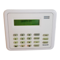
Four-Wire Circuit Reset Operation (Fig. 17).
Reset four-wire smoke detectors from the keypad by
entering the disarm code and pressing the FIRE
RESET mode numeric key.
The reset period is approximately 60 seconds, after
which the Fire loop is returned to service. During the
60 seconds, the power is removed and the Fire loop
is disabled. At the end of the 60 seconds, the alarm
condition will repeat if the detector still detects
smoke.
15 16 17 18 19
20
TB1
+13.8 VDC
AUX OUT
BELL
COM
P8 –
P8 +
M10901
4-WIRE SMOKE DETECTOR HOOK-UP
COM
AS/RBK-624
NO
COM
VIOLET
NO
SMOKE
DETECTOR
–
+
1
3
COM NO
COM NO
SMOKE
DETECTOR
–
+
1
2
1
2
3
RED/
WHITE
BLACK
RED
HONEYWELL EM1000
#4-WIRE SMOKE DETECTORS:
SENTORL ESL 449CT OR
DETECTION SYSTEMS INC. DS250 SENSOR AND MB4W BASE
END-OF-LINE MODULE:
HONEYWELL EM1000
SMOKE RESET RELAY:
ALARMSAF RELAY (PART NO. AS/RBK-624) IS REQUIRED AND MUST
BE PROCURED SEPARATELY FOR PROPER OPERATION OF THE
FOUR-WIRE SMOKE DETECTOR SYSTEM.
Fig. 16. Wiring diagram for four-wire hardwired smoke
detectors.
AS/RBK-624
BATTERY
TB1
J1
S1
M10904
Fig. 17. Installation of smoke alarm reset relay.
 Loading...


