HONEYWELL 7000 SOLID STATE ALARM SYSTEM
69-1192—1
17
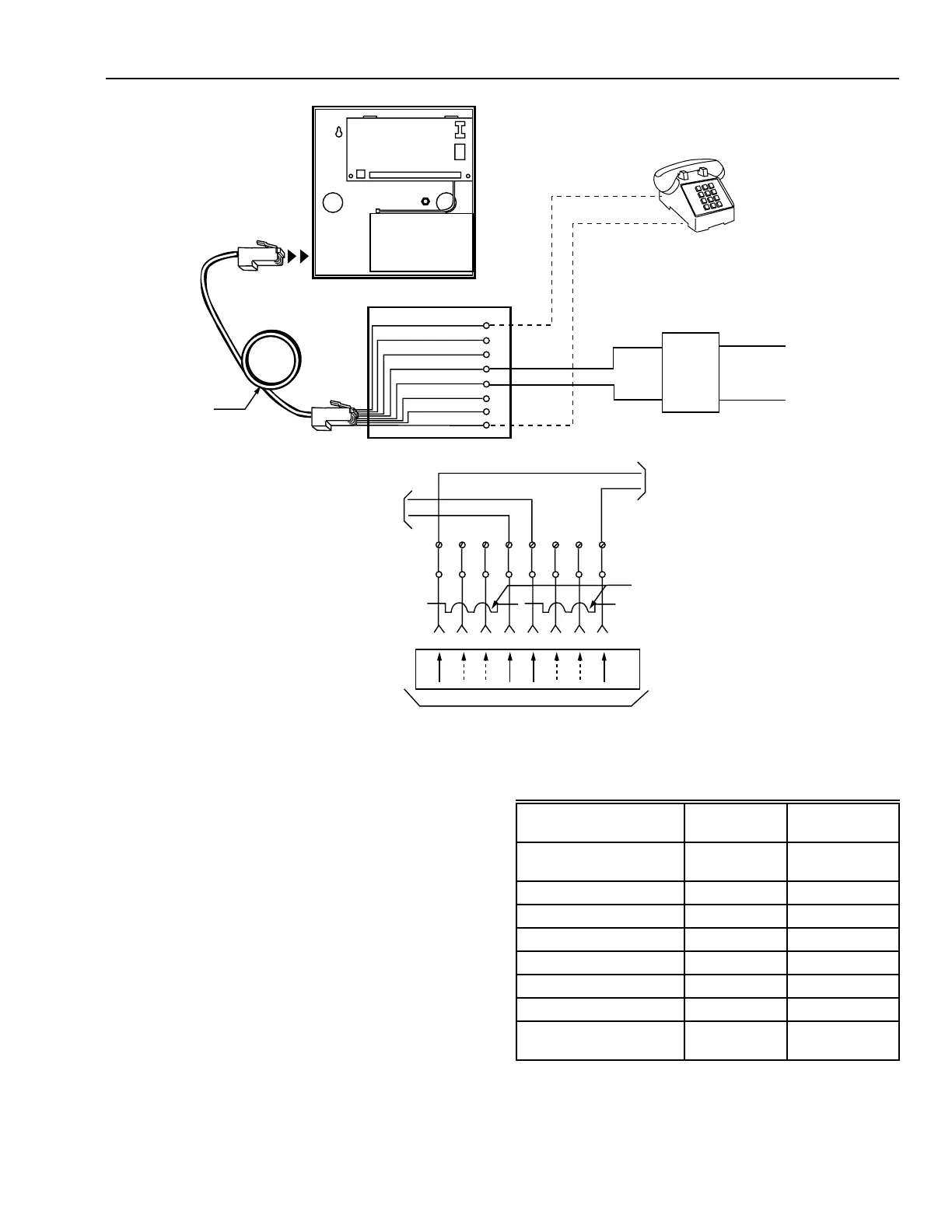
Fig. 19. Simplified telephone company wiring diagram.
BATTERY
TB1
J1
S1
M10906
BROWN
BLUE
YELLOW
GREEN
RED
BLACK
ORANGE
GRAY
8
7
6
5
4
3
2
1
87654321
TIP
(GREEN)
RING
(RED)
INCOMING PHONE
LINE FROM
TELEPHONE POLE
LIGHTING SURGE
PROTECTOR
(OPTIONAL)
HOUSE
PHONE
CONTROL PANEL
RJ31X CORD
RJ31X JACK
TO TELCO
NETWORK
8-CONDUCTOR
CORD
TO TELCO
WIRING ALL
LOCAL PHONES
SHORTING BAR
SHORT REMOVED
ON PLUG INSERTION
MINIATURE
8 POSITION
SERIES JACK
MINIATURE
8 POSITION PLUG
TO REGISTERED TERMINAL EQUIPMENT
T
T
R
R
R1
R1
T1
T1
Battery Calculations
The Honeywell 7000 System can have from one to
four 7AH standby batteries. The number of batteries
needed is a function of the size of the system. The
formula used to calculate battery capacity is:
Normal current (Amps) x 24 hours + Alarm current (Amps)
x 1/15 hours + 10% = Capacity needed (AH)
Divide the ampere-hour result by seven to obtain the
number of 7AH batteries needed for the system.
Table 8 gives current usage, normal and alarm, for
the devices in the system. Adding the normal and
alarm currents of the system and using the above
formula, determine the number of batteries needed.
Table 7. Current use of Honeywell 7000 System devices.
Device
Normal
Current (mA)
Alarm Current
(mA)
Control Panel with 8
Points
90 90
Keypad 120 120
PEM 60 60
RFEM 60 60
RF Receiver 50 50
Horn 0 950
2-Wire Smoke Detectors 0 25
Miscellaneous/AUX
Devices
**
* Miscellaneous/AUX devices can be relays, IR, etc. from the
AUX terminal, additional HBus devices (HSP, PEM, etc.), or
four-wire smoke detectors. Use the manufacturer current
ratings for this calculation.
 Loading...


