EC7830A, RM7830A, EC7850A, RM7850A 7800 SERIES RELAY MODULES
13 66-1092—06
Explosion hazard.
Can cause serious injury or death.
Be sure all manual fuel shutoff valves are closed.
Mounting Other System Components
(Fig. 5)
Refer to the applicable specifications for mounting other
system components.
PRINCIPAL TECHNICAL
FEATURES
The EC/RM7830A or EC/RM7850A Relay Module provide all
customary flame safeguard functions as well as significant
advancements in safety, annunciation, and system
diagnostics.
Safety Shutdown (Lockout) Occurs
If:
1. INITIATE Period
a. Purge card is not installed or removed.
b. Purge card is defective.
c. Configuration jumpers were changed (after 200
hours of operation).
d. AC line power errors, see Operation.
e. Four minute INITIATE period is exceeded.
2. STANDBY Period
a. Flame signal is present after 40 seconds.
b. Preignition Interlock is open an accumulative time of
30 seconds.
c. Airflow Switch feature is enabled and the Airflow
Switch is closed for 120 seconds with Limits and
Burner Control closed.
d. Ignition/pilot valve/intermittent pilot valve terminal is
energized.
e. Main valve terminal is energized.
f. Internal system fault.
g. Purge card is not installed or removed.
h. Purge card is defective.
i. Lockout Input opens during STANDBY.
3. PURGE Period
a. Preignition Interlock opens anytime during purge.
b. Flame signal detected during purge.
c. High Fire Switch fails to close within five minutes
after the firing rate motor is commanded to drive to
high fire position at start of purge (EC/RM7850A).
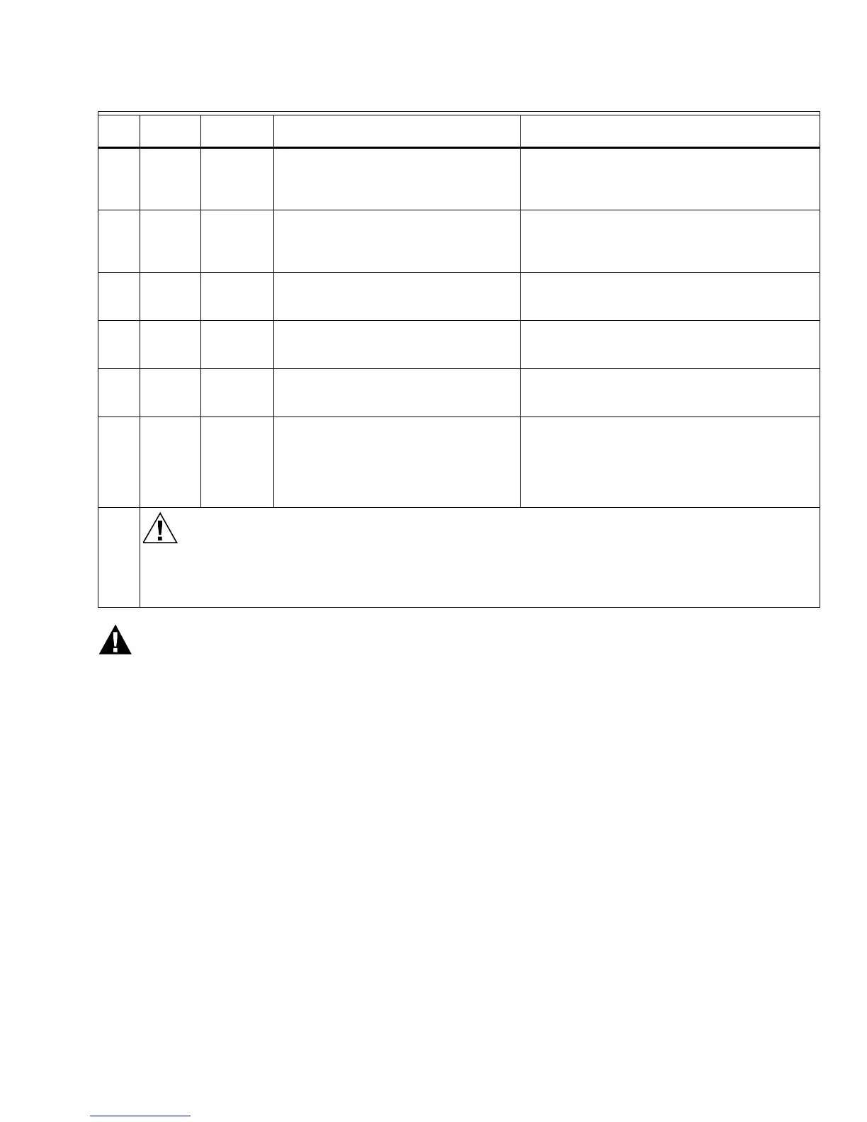
9 4-21 — Same test as no. 4 for connections to
terminal 8. If using direct spark ignition,
check the first stage fuel valve(s) instead
of the pilot valve.
Same as test no. 4. If using direct spark ignition,
check the first stage fuel valve(s) instead of the pilot
valve.
10 4-9 — Automatic main fuel valve(s) open(s). If
using direct spark ignition on a model with
intermittent pilot on terminal 21, check the
optional second stage fuel valve, if used.
1. Listen for and observe operation of the main
fuel valve(s) and actuator(s).
2. Valve(s) and actuator(s).
11 12-13 18-L2 Voltmeter reads line voltage, then zero
volts on terminal 18 after motor starts
driving open.
1. Low Fire Start Switch.
2. Firing rate motor and transformer.
12 12-13 19-L2 Firing rate motor drives open; line voltage
at terminal 19 after motor is in High Fire
position.
1. High Fire Purge Switch.
2. Firing rate motor and transformer.
13 14-13 19-L2 Firing rate motor drives closed; zero volts
at terminal 19 after motor starts driving
closed.
1. Low Fire Start Switch.
2. Firing rate motor and transformer.
14 15-13 — 1. Raise setpoint of Series 90
controller—firing rate motor should
drive toward open.
2. Lower setpoint of Series 90
controller—firing rate motor should
drive toward closed.
1. Series 90 controller.
2. Firing rate motor and transformer.
Final
Equipment Damage Hazard.
Failure to remove jumpers can damage equipment.
After completing these tests, open the master switch and remove all test jumpers from the subbase terminals.
Also, remove bypass jumpers from the low fuel pressure limits (if used).
Table 6. EC/RM7850A Static Checkout. (Continued)
Test
No.
Test
Jumpers Voltmeter Normal Operation If Operation is Abnormal, Check These Items

 Loading...


