EC7830A, RM7830A, EC7850A, RM7850A 7800 SERIES RELAY MODULES
Automation and Control Solutions
Honeywell International Inc.
1985 Douglas Drive North
Golden Valley, MN 55422
customer.honeywell.com
® U.S. Registered Trademark
© 2011 Honeywell International Inc.
66-1092—06 M.S. Rev. 07-11
Printed in U.S.A.
changed after the 200 hours occur, the relay module locks out.
This safety function assures that the relay module cannot be
modified after it is installed in a particular location.
If JR3 (Airflow Switch) is intact (no Airflow Switch), then a
jumper must be installed between terminals 6 and 7. If JR3 is
clipped (Airflow Switch is present), the relay module locks out
if it detects a jumper between terminals 6 and 7.
SERVICE NOTE:Clipping and removing a site-configurable jumper enhances the level of safety.
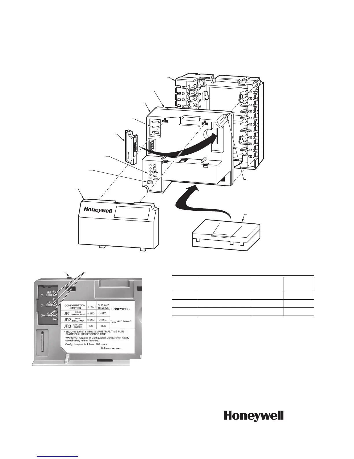
Fig. 5. EC/RM7830A and EC/RM7850A Relay Modules exploded view.
Fig. 6. Selectable site-configurable jumpers.
Table 7. Site-configurable jumper options.
a
EC7850A1148 or RM7850A1035
Intact—3 seconds Clipped—2 seconds
IMPORTANT
Clipping site-configurable jumpers after 200 hours of
operation results in a nonresettable Code 110,
LOCKOUT. The relay module must be replaced.
Flame Signal Measurement
Measure the flame signal at the appropriate times as defined
in the applicable flame amplifier specifications.
HONEYWELL
DUST
COVER
PURGE
TIMER
WIRING
SUBBASE
CAPTIVE
MOUNTING
SCREW
RUN/TEST
SWITCH
CONFIGURATION
JUMPERS
RELAY
MODULE
SEQUENCE
STATUS
LED PANEL
RESET
BUTTON
FLAME
AMPLIFIER
BURNER CONTROL
M15187A
RUN/TEST SWITCH
SELECTABLE CONFIGURATION
JUMPERS
M7701B
Jumper
Number Description Intact Clipped
JR1 First Safety Time 5 seconds
a
3 seconds
a
JR2 Main Trial Time 5 seconds 3 seconds
JR3 Airflow Switch No Yes

 Loading...


