EC7830A, RM7830A, EC7850A, RM7850A 7800 SERIES RELAY MODULES
11 66-1092—06
Electrical Shock Hazard.
Can cause severe injury, death, or property
damage.
Use extreme care when testing the system. Line
voltage is present on most terminal connections when
power is on. Ensure proper selection of configuration
jumpers before starting the burner operation.
Equipment Damage Hazard.
Improper testing can cause equipment damage.
Do not perform a dielectric test with the relay module
installed. Internal surge protectors break down and
conduct a current. This can cause the relay module to
fail the dielectric test or destroy the internal lightning
and high current protection.
1. Open the master switch before installing or removing a
jumper on the subbase.
2. Before continuing to the next test, be sure to remove
test jumper(s) used in the previous test.
3. Replace all limits and interlocks that are not operating
properly. Do not bypass limits and interlocks.
Equipment Recommended
Voltmeter (1M ohm/volt minimum sensitivity) set on the 0 to
300 Vac scale and two jumper wires, No. 14 wire, insulated,
12 in. (304.8 mm) long with insulated alligator clips at both
ends.
General Instructions
1. Perform all applicable tests listed in the Static Checkout,
Table 4 or 5, in the order listed.
2. Make sure all manual fuel shutoff valves are closed.
3. For each test, open the master switch and install the
jumper wire(s) between the subbase wiring terminals
listed in the Test Jumpers column.
4. Close the master switch before observing operation.
5. Read the voltage between the subbase wiring terminals
listed in the Voltmeter column.
6. If there is no voltage or the operation is abnormal, check
the circuits and external devices as described in the last
column.
7. Check all wiring for correct connections, tight terminal
screws, correct wire, and proper wiring techniques.
8. Replace all damaged or incorrectly sized wires.
9. Replace faulty controllers, limits, interlocks, actuators,
valves, transformers, motors and other devices, as
required.
10. Make sure normal operation is obtained for each
required test before continuing the checkout.
11. After completing each test, be sure to open the master
switch and remove the test jumper(s).
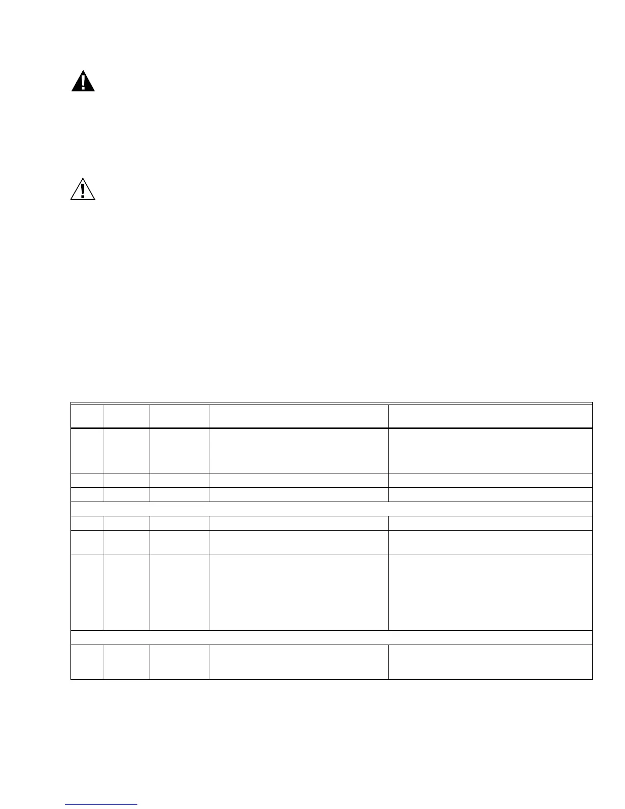
Table 5. EC/RM7830A Static Checkout.
Test
No.
Test
Jumpers Voltmeter Normal Operation
If Operation is Abnormal, Check the Items
Listed Below
1 None 5-L2 Line voltage at terminal 5. 1. Master switch.
2. Power connected to the master switch.
3. Overload protection (fuse, circuit breaker,
etc.) opened the power line.
2 None 17-L2 Line voltage at terminal 17. Preignition interlocks.
3 5-16 — Alarm (if used) turns on. Alarm.
NOTE: Disconnect horn at this time (if used).
4 5-16 2-20 Line voltage at terminal 20. Limits in Lockout Circuit.
5 5-16 2-6 Line voltage at terminal 6. 1. Recycle limits.
2. Burner control.
65-16
5-4
2-7 1. Fan (Burner Motor or Blower) starts.
2. Line voltage at terminal 7.
1. Fan circuit.
a. Manual Fan Switch.
b. Fan power supply, overload protection
and starter.
c. Fan.
2. Running Limits or Airflow Switch (LD2
input).
NOTE: Remove jumpers and reconnect alarm (if used).
7 5-10 — Ignition spark (if ignition transformer is
connected to terminal 10).
1. Watch for spark or listen for buzz.
a. Ignition electrodes are clean.
b. Ignition transformer is okay.

 Loading...


