5 65-0120—1
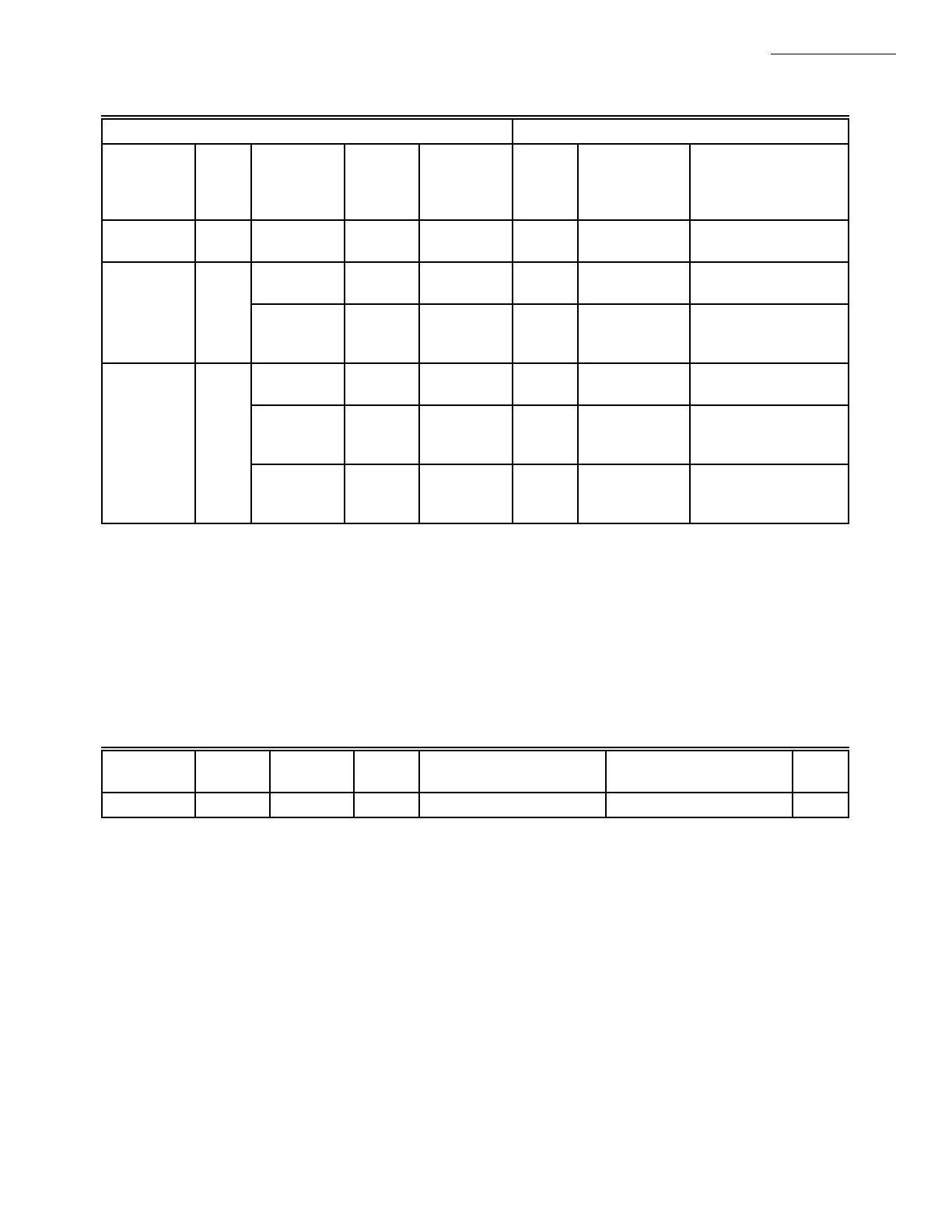
TABLE 2—FLAME DETECTION SYSTEMS (Continued)
Plug-in Flame Signal Amplifiers Applicable Flame Detectors
Type Color
Self-
Checking Model
Flame
Failure
Response
Time Fuel Type Models
Rectification
(Continued)
Green Dynamic
Self-Check
R7847C
e
3 sec Gas, oil,
coal
Ultraviolet
(Purple Peeper)
C7012E,F.
Infrared Red No R7848A 3 sec Gas, oil,
coal
Infrared (Lead
Sulfide)
C7015.
Dynamic
AMPLI-
CHECK™
R7848B
d
3 sec Gas, oil,
coal
Infrared (Lead
Sulfide)
C7015.
Ultraviolet Purple No R7849A .8 or 3 sec Gas, oil Ultraviolet
(Minipeeper)
C7027, C7035,
C7044.
c
Dynamic
AMPLI-
CHECK™
R7849B
d
.8 or 3 sec Gas, oil Ultrviolet
(Minipeeper)
C7027, C7035,
C7044.
c
Blue Dynamic
Self-Check
R7886A
e
3 sec Gas, oil,
coal
Ultraviolet
(Adjustable
Sensitivity)
C7076.
RM7838B
SPECIFICATIONS
a
Order flame rod separately; see holder Instructions.
b
Use only Honeywell Photocell, part no. 38316.
c
The C7012A,C, C7027, C7035 and C7044 flame detectors should be used only on burners that cycle on-off at least once every
twenty-four hours. Appliances with burners that remain on for twenty-four hours continuously or longer should use the
C7012E,F Flame Detector with the R7847C Amplifier or the C7076A Flame Detector with the R7886A Amplifier as the
ultraviolet flame detection system.
d
Circuitry tests the flame signal amplifier at least 12 times a minute during burner operation and shuts down the burner if the
amplifier fails.
e
Circuitry tests all electronic components in the flame detection system (amplifier and detector) 12 times a minute during
burner operation and shuts down the burner if the detection system fails.
SEQUENCE TIMING FOR NORMAL OPERATION:
General Purpose Interface ControlBus™ Module—
part no. QS7850A1006.
Electrical Access Slot Covers—part no. 221779
Remote Display Mounting Bracket—part no. 203765.
Tester—part no. A7800A1002.
Remote Display Power Supply—part no. 203968A
Plug-in.
Sixty-inch Extension Cable Assembly—
part no. 221818A.
NEMA 4 Display Enclosure —part no. 204718A.
NEMA 4 Display Enclosure with Remote Reset
Button—part no. 204718C
Flame Simulator
—Ultraviolet—part no. 203659.
—Rectification—part no. 123514A.
Device Initiate Standby Purge Pilot Flame Establishing
Period (PFEP)
Main Flame Establishing
Period (MFEP)
Run
RM7838B 10 sec. * ** 4/10 10 *** *
* STANDBY and RUN can be an infinite time period.
** PURGE will be determined by which ST7800A Purge Card is selected.
*** Immediate or deferred main flame.
ACCESSORIES:
Optional:
ControlBus 5-Wire Connector—part no. 203541.
COMBUSTION SYSTEM MANAGER™—
part no. ZM7850A1001.
Communication Interface Base Unit—
part no. Q7700A1014.
Communication Interface ControlBus™ Module—
part no. QS7800A1001.
Keyboard Display Module—part no. S7800A1001.
DATA CONTROLBUS MODULE™—
part no. S7810A1009.
Remote Reset Module—part no. S7820A1007.
Expanded Annunciator—part no. S7830A1005.

 Loading...


