15
EN2R--9023 9705R0--NE
LINE
NEUTRAL
EC7850 with rectification amplifier
N3
AL
4
L1
5
FAN
6
RT
7
LD2
8
PV1
9
MV
10
IGN
F
flame--
signal
G
ground
13
COM
12
HI
15
LOW
14
MOD
16
C.V.
18
ES1
17
ES2
19
ES3
20
LOS
21
PV2
22
SHTR
EARTH
ALARM
FAN
flame--rod
H.D.
ign.
P.S .
(intermittent)(interrupted)
A4021A
GPS
9
V1INLGPS / HD
10
OUT
11
VENT
13 15
V1OUT
16
RBHD
12
HD--OUT
1432
NO
1 7
V2IN
8
V2OUT
4 5 6
NNN
ALARM
IN
RESET
LINEext.
EXTERNAL
RESET
gas supply
V1 V2
PV
G.P.S.
HI
LO
Lock--out switch
L.G.P.S.
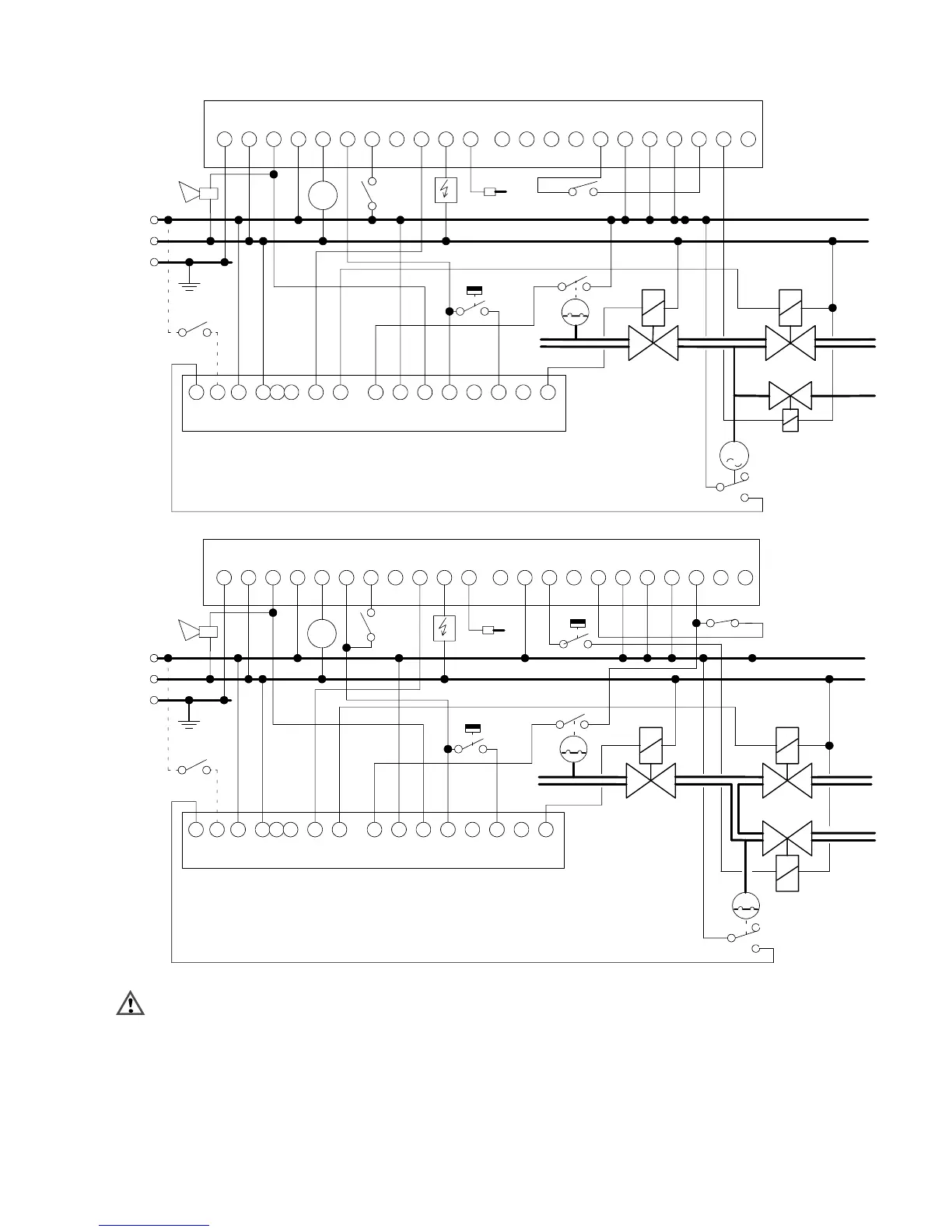
Fig. 16. Wiring diagram A4021A -- EC7850, post--configuration: intermittent system with 3--valve configuration
LINE
NEUTRAL
EC7850
N3
AL
4
L1
5
FAN
6
RT
7
LD2
8
PV1
9
MV
10
IGN
F
flame--
signal
G
ground
13
COM
12
HI
15
LOW
14
MOD
16
C.V.
18
ES1
17
ES2
19
ES3
20
LOS
21
PV2
22
SHTR
EARTH
ALARM
FAN
flame--rod
H.D.
ign.
P.S .
(intermittent)(interrupted)
A4021A
GPS
9
V1INLGPS / HD
10
OUT
11
VENT
13 15
V1OUT
16
RBHD
12
HD--OUT
1432
NO
1 7
V2IN
8
V2OUT
4 5 6
NNN
ALARM
IN
RESET
LINEext.
EXTERNAL
RESET
gas supply
V1 V2
HI
LO
By--pass valve
Vb
LOCK--OUT Switch2--stage
L.G.P.S.
L.G.P.S.
Fig. 17. Wiring diagram A4021A-- EC7850 with by--pass valve, post configuration
WARNING
These are general wiring diagram and have not been
approved yet by an official approval body. Depending
on the application and used ignition controller special
wiring diagrams maybe required.
 Loading...