EasyManuals Logo

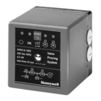
Honeywell A4021 Series User Manual

Honeywell A4021 Series
21 pages
To Next Page IconTo Next Page
To Previous Page IconTo Previous Page
Page #17 background imageLoading...
Page #17 background image
Operate burner
Valve 1
Valve 2
Heat demand
Alarm
Valve 2
Power
Run
OK
Valve 1
Pressure
(between V1 and V2
Alarm output
Timings (sec.)
*= depends on OS #
ALARM MODE
ERROR
HEAT
V1
ERROR
5*
5*
TEST MODE
TEST
V1
V2
START
OPEN
TEST
V2
V1
OPEN
STANDBY
SELF
RUN MODE
OPERATE
BURNER
(valves operated by
ignition controller)
WAIT
START--UP
3*
3*
25 * 25 *
TEST
GPS
GPS
TEST
ERROR
SELF--
Modes
States
0 1 2 3 4 5 6 7 8 9 11 12 14 15
DEMAND
HIGH
TEST
STANDBY
Line voltage
TEST
LOW
FOR
O
P
E
R
A
T
I
O
N
Sequence of operation
V2
ERROR
10
V2
13
FAILING/
LEAKING
V1
FAILING/
LEAKING
WARNING
No standard valve proving after lock--out of the ignition controller
= blinking LED= LED is off = LED on
16
EN2R--9023 9705R0--N
E

Questions and Answers:

Question and Answer IconNeed help?

Do you have a question about the Honeywell A4021 Series and is the answer not in the manual?

Honeywell A4021 Series Specifications

General IconGeneral
BrandHoneywell
ModelA4021 Series
CategoryControl Unit
LanguageEnglish

Related product manuals