Installation and Operations Guide
|
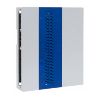
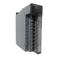
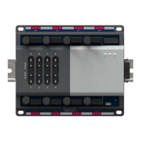
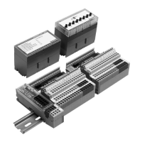
About the ACM-VLX, VLX, EXPs, and AXMs
© Honeywell. All Rights Reserved. LT-VLXEXPAXMIOG Rev. 01
21
After a VLX/ACM-VLX is configured and programmed using a Compass
operator workstation, it can operate in a stand-alone capacity indefinitely.
The VLX/ACM-VLX provides a robust and customizable I/O configuration for
systems with a large number of control points and requirements for local
execution of DDC, scheduling, and other automation features. Typical
applications include large air-handling units, motor control centers, and chiller
plants. A single VLX/EXP or VLX/AXM assembly replaces the functionality of
multiple VLCs with a global controller. It can also operate in concert with a
global controller.
The numerical designation of an EXP/AXM conveys information about its I/O
configuration. The first number indicates the number of universal inputs, the
second indicates the number of binary outputs, and the third indicates the
number of analog outputs.
What’s in the VLX/ACM-VLX
• Capabilities.
VLX: Support up to 10 BACnet compliant devices on its MS/TP trunk.
It can also host schedules, trendlogs, and alarms.
ACM-VLX: Supports a full network of VLCs on one of it other 485
networks.
• Procedures for initial configuration and I/O setup.
VLX: Connect with an AC-2650 and use HyperTerminal to configure
network and firmware settings. See “Initial firmware and operator
workstation setup” on page 40. However, the VLX does not support I/O
configuration through this interface or through VisualLogic. Use an
operator workstation to configure special-purpose AVs. See “Setting up
inputs” on page 53. Data display templates are provided for this
purpose. See “Appendix C: Compass operator workstation templates”
on page 76.
ACM-VLX: Configure using Compass Device Manager.
• Power and BO wiring. BO power is isolated from EXP, AXM, and
VLX/ACM-VLX power. A separate ground lug connects to panel
ground. See Figure 13 on page 17 and “Single-point grounding” on
page 25.
• 4-20 mA wiring. No external 250 Ohm resistor required. See
“Universal inputs (AIs, BIs)” on page 35.
• Manual output overrides: H-O-A switches and trimpots. Hand-Off-
Auto switches enable local override of binary and analog outputs. Status
values are available in software. See “Using H-O-A switches and
AXM-1048 EXP-1048
Te n inputs
Four binary outputs
Eight analog outputs
 Loading...
