Installation and Operations Guide
|
ACM-VLX/VLX/EXP/AXM
34
© Honeywell. All Rights Reserved. LT-VLXEXPAXMIOG Rev. 01
ungrounded side of the 24 V relays or other 24 VAC loads. See Figure 13 on
page 17 for a wiring diagram.
Cable Use 18 AWG cable for BO connections in most applications.
Providing isolated BO power BOs on the EXP/AXM require a power supply
separate from the EXP/AXM or VLX unit power supply. This isolates the
switched-load BO power from the EXP/AXM/VLX unit operating power, which
helps to prevent interference and electrical feedback noise from the switched
outputs affecting EXP/AXM operation.
Each EXP/AXM BO can deliver a maximum of 12 VA (24 VAC @ 0.5A). Each
EXP/AXM that supports BOs has a “BO MAX. LOAD” listed on the cover,
which indicates the maximum consumption in VA when all BOs are energized.
Always use this BO MAX. LOAD figure to determine the size and number of
transformers required to power BO loads. Even if all BOs are not currently used,
this ensures that the transformer(s) will not need to be exchanged to
accommodate future additions.
Any number of BOs can share a transformer, as long as the transformer is
adequately sized. See “Transformer sizing” on page 28.
A fast fuse is recommended on the hot leg of the 24 VAC BO power circuit to
prevent equipment damage from a shorted or faulty relay, a failed damper
actuator, a failed transformer, or other wiring or system faults. Size the fuse at
125% of the sum of all loads powered by the transformer.
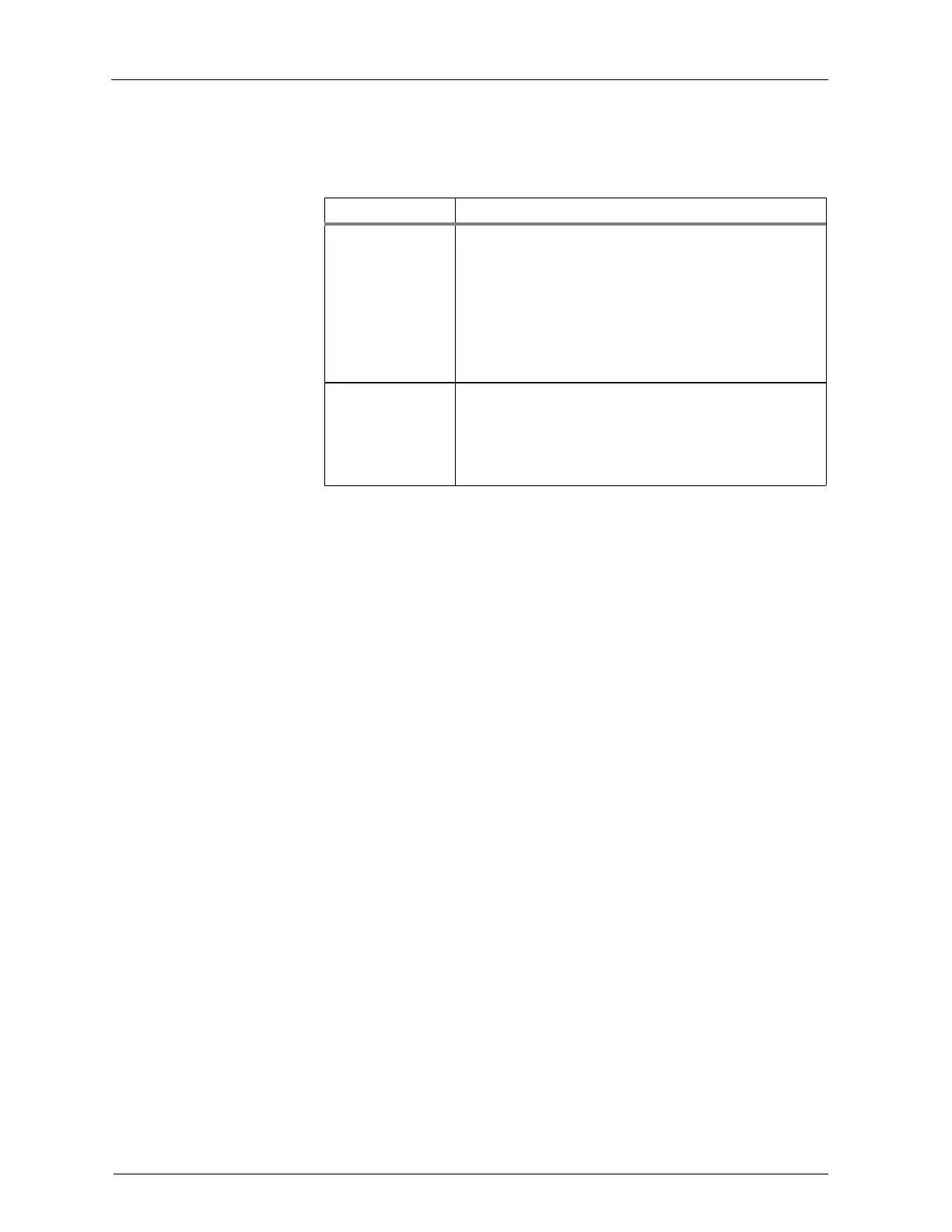
Table 6 EXP/AXM BO te rminals
Te rminal labe l De s c ription
HOT <A|B|C|D> Use to terminate the hot leg of the 24 VAC circuit. This
terminal has switched, software-controlled, onboard
connections to the BO n terminals adjacent to it. For
transformer sharing between BO banks, jumper HOT
terminals together with 18 AWG wire. See Figure 13 on
page 17. DO NOT CONNECT THIS TERMINAL TO
GROUND OR EQUIPMENT DAMAGE WILL
RESULT.
BO n Use to connect to the ungrounded side of the 24 V relay
or other 24 VAC load. DO NOT CONNECT THIS
TERMINAL TO GROUND AND MAINTAIN
POLARITY FOR ALL CONNECTED LOADS OR
EQUIPMENT DAMAGE WILL RESULT.
 Loading...


