Installation and Operations Guide
|
Key illustrations
© Honeywell. All Rights Reserved. LT-VLXEXPAXMIOG Rev. 01
9
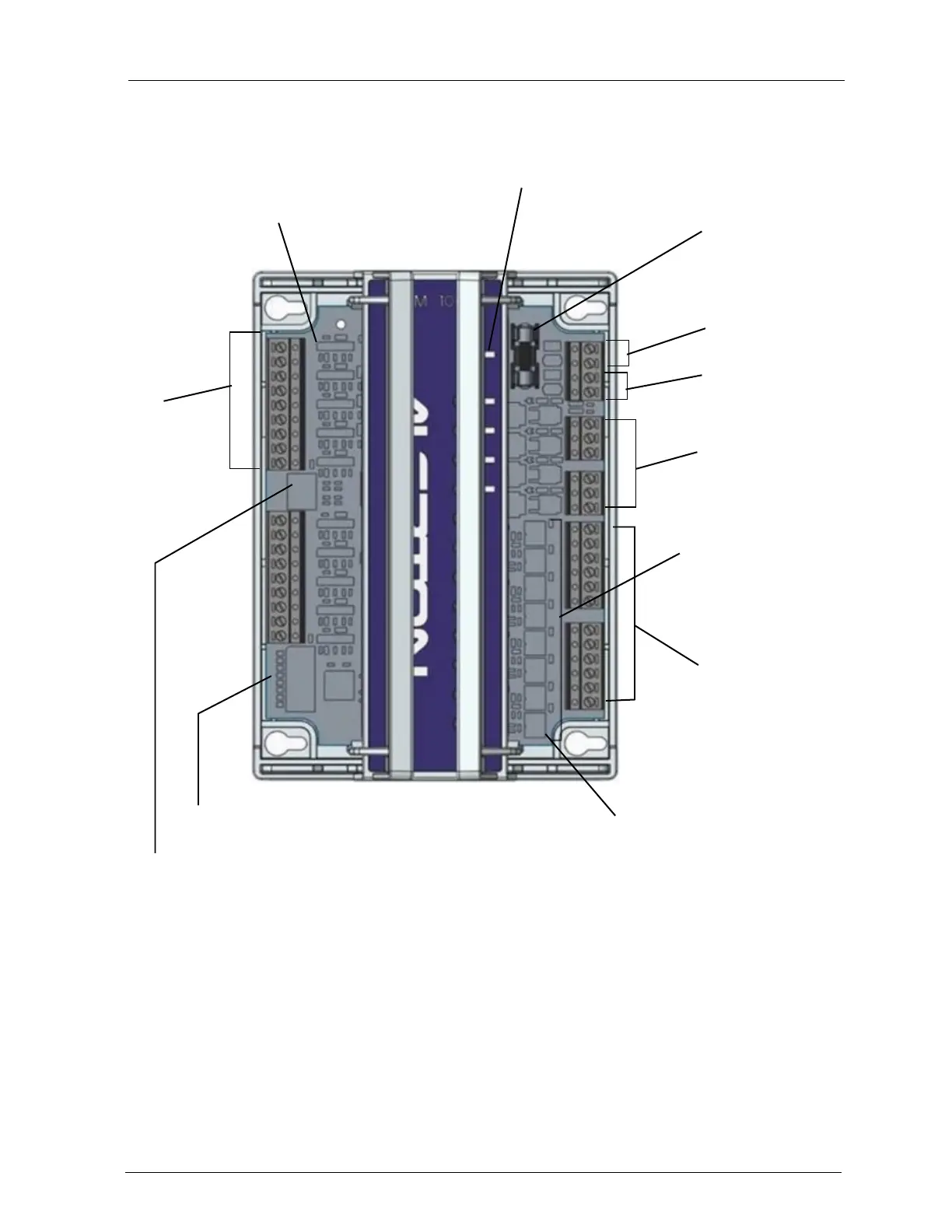
Figure 4 Typical AXM (I/O e xpans ion module ), AXM-1048 s hown
IN and COM
terminals for
connecting to
universal
inputs.
Input configuration
jumpers for each input are
set according to input type.
Status LED indicates 24VAC
and communications status.
Replaceable fuse.
Output LEDS indicate
operational status of
corresponding output.
24VAC power.
Maintain polarity.
AXM/EXP
communications.
Maintain polarity.
BO banks with HOT
terminals.
Trimpots for tuning AOs
from 0-100% when H-O-A
is in the H position.
AO terminals.
SW2 for AO configuration.
Each switch corresponds to an AO.
SW1 for AXM address. Use switched 1-3 to set
AXM address in the range 0-7.
Hand-Off-Auto (H-O-A) switches for
each output for manual override of
output status.
 Loading...


