C6097 · Edition 01.24
EN-2
2 CHECKING THE USAGE
Gas pressure switches C6097 for monitoring in-
creasing and decreasing gas or air pressure.
C6097A: switches with falling pressure,
C6097B: switches with rising pressure.
Positive pressure
Negative
pressure
C6097A
Gas, air, flue gas,
biogas
Air, flue gas
C6097B
Gas, air, flue gas,
biogas
Air, flue gas
This function is only guaranteed when used within
the specified limits– see page 6 (9 Technical
data). Any other use is considered as non-compliant.
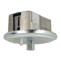
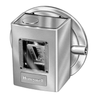
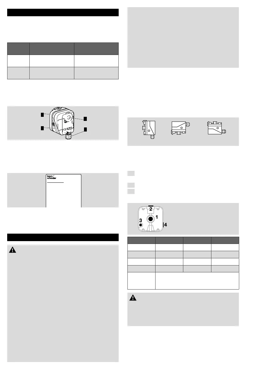
2.1 Part designations
1
2
3
4
1 Upper housing section with cover
2 Lower housing section
3 Hand wheel
4 M16 cable gland
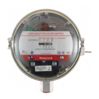
2.2 Type label
C6097
CE
Made in Germany
Max. inlet pressure = withstand pressure, mains
voltage, ambient temperature, enclosure: see type
label.
3 INSTALLATION
CAUTION
Please observe the following to ensure that the
C6097 is not damaged during installation and
operation:
– Dropping the device can cause permanent
damage. In this event, replace the entire device
and associated modules before use.
– Use approved sealing material only.
– Continuous operation with gases containing
more than 0.1%-by-vol. H
2
S or ozone
concentrations exceeding 200µg/m
3
accelerate
the ageing of elastomer materials and reduce
the service life.
– Check max. ambient temperature– see page
6 (9 Technical data).
– When using silicone tubes, only use silicone
tubes which have been sufficiently cured.
– Vapours containing silicone can adversely affect
the functioning of electrical contacts.
– Condensation or vapours containing silicone
must not be allowed to get into the housing. At
subzero temperatures, malfunctions/failures due
to icing can occur.
– When installing outdoors, place the C6097 in a
roofed area and protect from direct sunlight
(even IP65 version).
– Avoid strong impact on the unit.
– In case of highly fluctuating pressures, install a
damping nozzle/restrictor orifice.
Installation position
➔ Installation position as required, preferably with
vertical diaphragm. Then the switching point p
S
corresponds to the scale value SK set on the
hand wheel. In other installation positions, the
switching pointp
S
will change and no longer cor-
respond to the scale valueSK set on the hand
wheel. Check the switching point.
p
s
= SK p
s
= SK + 18 Pa p
s
= SK - 18 Pa
➔ The C6097 must not be in contact with masonry.
Minimum clearance 25mm (1").
➔ Ensure that there is sufficient installation space.
➔ Ensure unobstructed view of the hand wheel.
1
Disconnect the system from the electrical power
supply.
2
Close the gas supply.
3
Ensure that the pipeline is clean.
Ports
1 and 2
Positive Pressure (Rp ¼" )
3 and 4
Negative Pressure (Rp
1
/8 " )
Pressure Connect Seal Free
Positive 1 2 3 or 4
Positive 2 1 3 or 4
Negative 3 4 1 or 2
Negative 4 3 1 or 2
Differential
1 or 2 for higher absolute pressure.
3 or 4 for lower absolute pressure.
Seal the ports that are not in use.
CAUTION
Ports 3 and 4 are connected to the upper dia-
phragm chamber with the micro switch. For this
reason, pipes carrying gas must not be connected
to port 3 or 4.
➔ A filter pad at port 4 protects the electrical
contacts in the C6097 from dirt particles in the
surrounding air or in the medium.
 Loading...