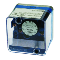
C6097 · Edition 01.24
EN-3
4 WIRING
CAUTION
– To ensure that the C6097 is not damaged
during operation, note the switching capacity,
see page 6 (9 Technical data).
In the case of low switching capacities, such as
24V, 8mA, for example, we recommend using an
RCmodule (22Ω, 1μF) in air containing silicone or
oil.
1
Disconnect the system from the electrical power
supply.
2
3
4
5
M16 x 1,5:
6
Wire as shown on the connection diagram.
7
Tighten the M16 gland.
➔ Contacts 3 and 2 close when subject to in-
creasing pressure. Contacts 1 and 3 close when
subject to falling pressure.
COM
3
NC
1
NO
2
NO
2
NC
1
COM
3
L1
5 ADJUSTMENT
➔ The switching point is adjustable via hand wheel.
1
Disconnect the system from the electrical power
supply.
2
Unscrew the housing cover.
➔ Once the settings have been adjusted success-
fully, fit the housing cover again. Note the tight-
ening torques, see page 6 (9 Technical data).
3
Connect an ohmmeter.
COM
3
NC
1
NO
2
NO
2
NC
1
COM
3
4
Set the switching point using the hand wheel.
5
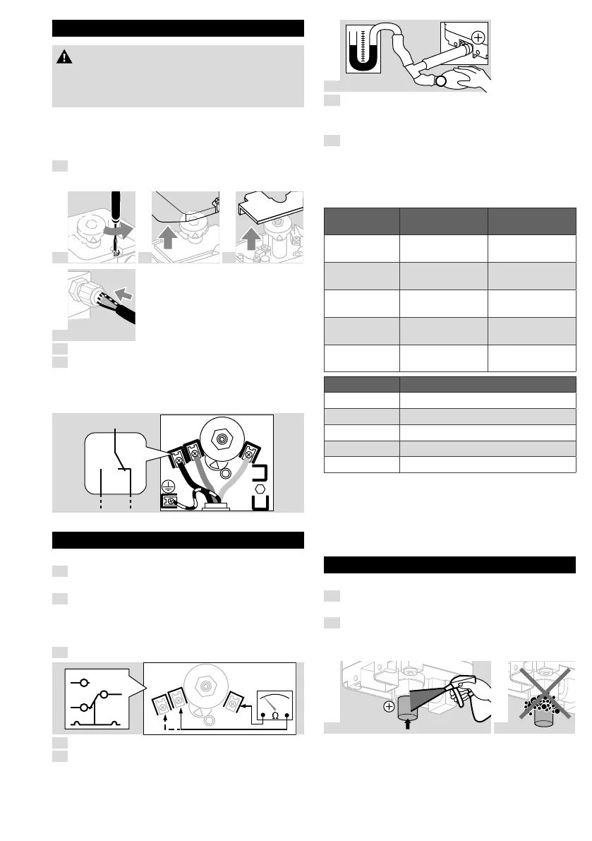
Connect a pressure gauge.
6
0
1 cm = 1 mbar
7
Apply pressure. In doing so, monitor the
switching point on the ohmmeter and the
pressure gauge.
8
If the C6097 does not trip at the desired
switching point, correct the adjusting range
using the hand wheel. Relieve the pressure and
repeat the process.
5.1 Adjusting range
Type
Adjusting
range
1)
Switching
differential
2)
C6097A4010
40–600Pa
(0.4–6mbar)
20–30Pa
(0.2–0.3mbar)
C6097A4110
100–1000Pa
(1–10mbar)
25–40Pa
(0.25–0.4mbar)
C6097A4210
0.25–5 kPa
(2.5–50mbar)
0.08–0.15 kPa
(0.8–1.5mbar)
C6097A4310
3–15 kPa
(30–150mbar)
0.3–0.5 kPa
(3–5mbar)
C6097A4410
10–50 kPa
(100–500mbar)
0.8–1.7 kPa
(8–17mbar)
Type Max. inlet pressure p
max.
C6097A4010 10 kPa (100mbar)
C6097A4110 50 kPa (500mbar)
C6097A4210 50 kPa (500mbar)
C6097A4310 60 kPa (600mbar)
C6097A4410 60 kPa (600mbar)
1) Adjusting tolerance = ±15% of the scale value.
2) Mean switching differential at min. and max. setting.
➔ Deviation from the switching point during testing
pursuant to EN1854 Gas and air pressure
switches: ±15%.
6 TIGHTNESS TEST
Check all gas ports used for tightness.
1
Shut off the downstream gas pipeline close to
the valve.
2
Open the valve and the gas supply.
➔ N
2
= 900mbar, max. 2bar (13psi, max. 29psi)
<15min.
3
N
2
4
 Loading...