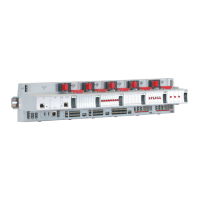
EAGLE CONTROLLER – INSTALLATION & COMMISSIONING INSTRUCTIONS
EN1Z-0970GE51 R1112 6
Ethernet Interface
The CLEA2000Bxx + CLEA2026Bxx are equipped with an
Ethernet / RJ45 socket featuring one LED.
J1 J8
ETHERNET / RJ45
socket
END
BIAS
MID
Fig. 6. Ethernet / RJ45 socket (CLEA2000Bxx +
CLEA2026Bxx, only)
This Ethernet / RJ45 socket is a 10/100-Mbaud Ethernet
interface permitting communication (as per IEEEC 802.3) on
BACnet IP networks.
LINK/ACT.
Fig. 7. Ethernet interface
NOTE: The Ethernet interface is usually earth-grounded. For
additional information on earth grounding, see also
“Appendix 1: Earth Grounding” on pg. 26.
LonWorks Connection
Via its USB 2.0 Host interface, the EAGLE Controller can be
connected to the IF-LON and thus to L
ONWORKS networks.
See also IF-LON External Interface Adapter – Mounting
Instructions (EN1Z-0974GE51).
IF-LON
Fig. 8. IF-LON
The IF-LON is equipped with a free-topology transceiver
(FTT10A) for communication (at a data transmission rate of
78 Kbaud) on L
ONWORKS® networks (using the LonTalk
protocol).
The L
ONWORKS network is insensitive to polarity, eliminating
the possibility of installation errors due to miswiring.
Different network configurations (daisy-chain, loop, and star
configurations, or any combination thereof) are possible. See
Excel 50/5000 L
ONWORKS Mechanisms (EN0B-0270GE51)
for details.
LEDs
The EAGLE Controller features the following LEDs:
Fig. 9. EAGLE Controller LEDs
Table 4. EAGLE Controller LEDs
symbol
color function, description
L1 yellow
application-specific LED indicating status
information (“Cooling Mode”, “Heating
Mode” “Service Interval” etc.)
L2 yellow
Indicates connection of operationally ready
device to USB 2.0 Host Interface.
Tx yellow
BACnet MS/TP status LED indicating
transmission of communication signals via
RS485-1
Rx yellow
BACnet MS/TP status LED indicating
reception of communication signals via
RS485-1
!
red
status LED indicating hardware problems,
lack of application, sensor failure, or Panel
Bus failure
green power LED
See also section “EAGLE Controller Troubleshooting” on
page 25 for a detailed description of the behaviors of the Tx
and Rx LEDs, the status LED, and the power LED and their
meanings.
RS485 Interfaces
General
The EAGLE features two RS485 interfaces located at the top
side of the EAGLE Controller:
RS485-1 (consisting of push-in terminals 24 [GND-1], 25,
and 26) is isolated and can be connected to a BACnet
MS/TP bus or a Panel Bus.
RS485-2 (consisting of push-in terminals 29, 30, and 31
[GND-2]) is non-isolated (i.e. GND-2 is internally
connected with terminal 1 [24V~0] and terminals 19+37
[system ground]) and can be connected to either a
BACnet MS/TP bus or a Panel Bus.

 Loading...


