CLCM1T,2T,4T,5T,6T WALL MODULES – INSTALLATION INSTRUCTIONS
MU1Z-0901GE51 R0416B 2
Mounting Procedure
1. Disassemble the cover as shown in Fig. 1.
2. CLCM2T,4T,5T,6T, only: Pull off the setpoint dial.
3. Mount the wall module onto the wall outlet box, or bore
wall holes as specified in Fig. 2 and mount the wall
module with appropriate screws.
4. Connect the wires to the terminal block according to
section “Wiring”.
5. CLCM2T,4T,5T,6T, only: Insert the setpoint dial and turn
it clockwise as far as possible.
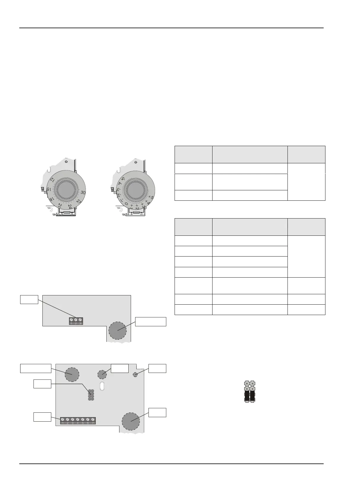
6. CLCM2T,4T,5T,6T, only: Make sure that the dial's
position is such that the 30 (°C absolute scale) or the +5
(°C relative scale) points to the right-hand side of the wall
module (see Fig. 3).
Fig. 3. Mounting position of setpoint dial
7. CLCM2T,4T,5T,6T, only: If the dial does not have the
correct position, pull the dial off again and reinsert it with
the correct orientation.
8. Remount the cover as depicted in Fig. 1 and make sure
that the tab on the underside engages.
Wiring
SETPOINT
(CLCM2T, only)
TERMINAL
BLOCK
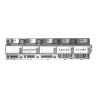
Fig. 4. CLCM1T,2T – mother board
SENSOR
SET PT
BYP/FAN
LED
BYP/RTN
LED/RTN
COM
A B
1: W77xx
2: W7753
3: XL500
1: W77xx
2: W7753
3: XL500
FAN SWITCH
(CLCM5T,6T, only)
BYPASS
BUTTON
OVERRIDE
LED
JUMPERS
TERMINAL
BLOCK
SETPOINT
Fig. 5. CLCM4T,5T,6T – mother board
Wiring with PANTHER
NOTE: You should always first connect the wall module and
only then install the PANTHER's software.
Wire the terminal blocks as follows:
1. Strip 5 mm of insulation from the conductor.
2. Insert the wire in the required terminal location and
tighten the screw to complete the termination.
3. Verify wall module wiring with Table 3 or Table 3 and
jumper setting with Fig. 6.
IMPORTANT
Screw-type terminal blocks are designed to accept no
more than one 1.5 mm
2
conductor.
Table 2. CLCM1T,2T terminal connections (PANTHER)
setpoint (not internally
connected)
Table 3. CLCM4T,5T,6T terminal connections (PANTHER)
LED (reserved for connection
to a 4…20 Vdc, 3.5 mA input)
When all wiring is complete, re-attach the cover of the wall
module as shown in Fig. 1 and make sure that the tab on the
underside engages.
Jumper Setting with PANTHER
The jumper setting of the CLCM4T,5T,6T with the PANTHER
is shown in Fig. 6.
1: W77xx
2: W7753
3. XL500
1: W77xx
2: W7753
3. XL500
Fig. 6. Jumper setting of CLCM4T,5T,6T (PANTHER)
 Loading...