CLCM1T, 2T, 4T, AND 6T WALL MODULES – INSTALLATION INSTRUCTIONS
Manufactured for and on behalf of the Environmental & Energy Solutions Division of Honeywell Technologies Sàrl, Rolle, Z.A. La Pièce 16, Switzerland by its Authorized Representative:
CentraLine
Honeywell GmbH
Böblinger Strasse 17
71101 Schönaich, Germany
Phone +49 (0) 7031 637 845
Fax +49 (0) 7031 637 740
info@centraline.com
www.centraline.com
Subject to change without notice
MU1Z-0901GE51 R0416B
Wiring with SERVAL
Wire the terminal blocks as follows:
1. Strip 5 mm of insulation from the conductor.
2. Insert the wire in the required terminal location and
tighten the screw to complete the termination.
3. Verify wall module wiring with Table 4 or Table 5 and
jumper setting with Fig. 7.
IMPORTANT
Screw-type terminal blocks are designed to accept no
more than one 1.5 mm
2
conductor.
Table 4. CLCM1T,2T terminal connections (SERVAL)
setpoint (not internally
connected)
Table 5. CLCM4T,5T,6T terminal connections (SERVAL)
LED (reserved for connection
to a 4…20 Vdc, 3.5 mA input)
When all wiring is complete, re-attach the cover of the wall
module as shown in Fig. 1 and make sure that the tab on the
underside engages.
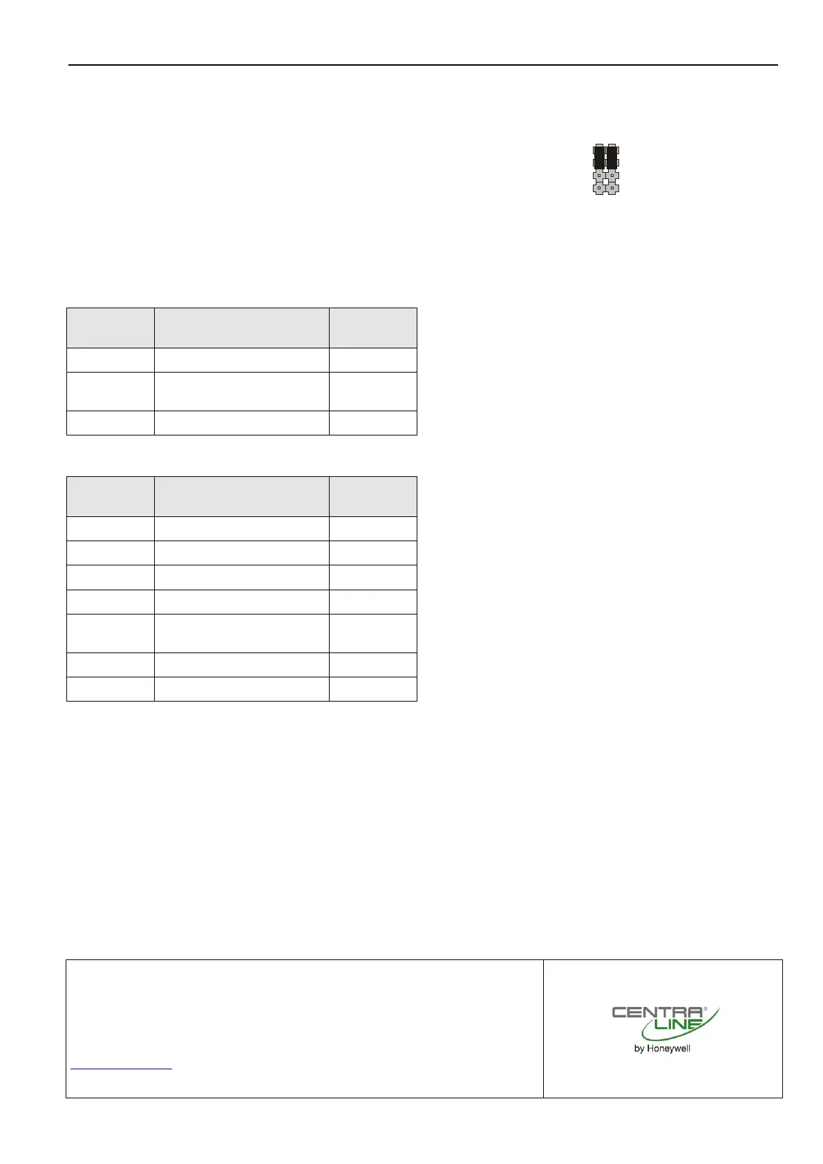
Jumper Setting with SERVAL
The jumper setting of the CLCM4T,5T,6T with the SERVAL is
shown in Fig. 7.
1: W77xx
2: W7753
3. XL500
1: W77xx
2: W7753
3. XL500
Fig. 7. Jumper setting of CLCM4T,5T,6T (SERVAL)
NOTE: This is the factory setting.
Limiters
The limiters can be used to restrict the range within which the
setpoint dial can be varied. After opening the housing, insert
the limiters approximately opposite the max. and min. values
of the desired temperature adjustment range.
 Loading...