CIPer
TM
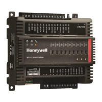
MODEL 30 EXPANSION IO MODULES - INSTALLATION INSTRUCTIONS
Each terminal can accommodate the following gauges of wire:
− Single wire: 22 AWG to 14 AWG solid or stranded
− Multiple wires: up to two 18 AWG stranded, with 1/4 watt wire-wound resistor
NOTES
• When attaching two or more wires to the same terminal, other than 14 AWG (2.0 sq mm),
be sure to twist them together. Deviation from this rule can result in improper electrical
contact (see Fig. 4).
Prepare wiring for the terminal blocks, as follows:
1. Strip 1/2 in. (13 mm) insulation from the conductor.
2. Cut a single wire to 3/16 in. (5 mm). Insert the wire in the required terminal location and tighten the screw.
3. If two or more wires are being inserted into one terminal location, twist the wires together a minimum of
three turns before inserting them (see Fig. 4).
4. Cut the twisted end of the wires to 3/16 in. (5 mm) before inserting them into the terminal and tightening
the screw.
5. Pull on each wire in all terminals to check for good mechanical connection.
Figure 4: Attaching two or more wires at terminal blocks.
 Loading...

