CIPer
TM
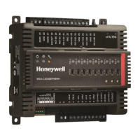
MODEL 30 EXPANSION IO MODULES - INSTALLATION INSTRUCTIONS
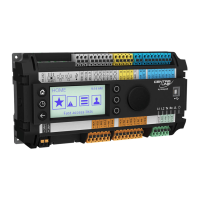
Universal inputs, UI-1 & UI-2
COM terminal for UI-1 & UI-2
Universal inputs, UI-3 & UI-4
COM terminal for UI-3 & UI-4
Universal inputs, UI-6 & UI-7
COM terminal for UI-6 & UI-7
Universal inputs, UI-8 & UI-9
COM terminal for UI-8 & UI-9
24V AC output from controller for DO devices
HOT (B) terminal. Supplies power to common side of controller’s DO-5 & DO-6
HOT (A) terminal. Supplies power to common side of controller’s DO-1 to DO-4
GND terminal for DO-1(A) & DO-2(A)
GND terminal for DO-3(A) & DO-4(A)
GND terminal for DO-5(B) & DO-6(B)
 Loading...

