TP970 SERIES CONVERTASTAT
®
KITS
Remove Powers Thermostat
1.
Loosen screws on each side to remove cover.
2.
Pull thermostat from the mounting plate.
3.
Cut tubes near connector and temporarily plug
main line to conserve air.
4.
Remove old mounting plate and retain screws.
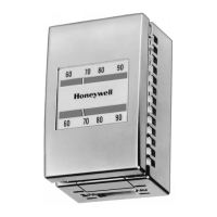
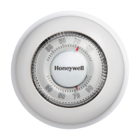
MCC POWERS
10 20 3015 25
2520
C2314
Fig. 3. Powers Thermostat.
Install New Thermostat
1.
Feed tubes through large adapter plate hole
(see Fig. 4).
2.
Match adapter plate holes to wall screw holes.
3.
Mount adapter plate using screws retained from
old mounting plate removal. Do not over-tighten
screws.
NOTE: If any wall screw holes coincide with
noncoded adapter plate holes (see
Fig. 4), proceed as follows. (If not,
continue with Step 4.):
a. With adapter plate away from the wall,
ream out or strip threaded holes by
tightening screws retained when
removing the old mounting plate.
Tighten with enough force so that the
screws move freely.
b. Remove and retain screws. If wall
screw holes are larger than #6,
enlarge adapter plate holes to allow
enough clearance for screws.
c. After removing temporary plug, push
tubes onto thermostat backplate (main
tube has air blowing out and must be
connected to the M barb connection on
backplate rear).
d. To remove thermostat cover, slowly
drive screws clockwise until cover is
free. To remove thermostat from
backplate, spread retaining clips and
separate (see Fig. 5).
e. Align and attach backplate and adapter
plate to mounting screw holes using
screws retained from stripping adapter
plate threads.
f. Proceed to Step 7.
NOTE: When adapting to a Johnson thermostat,
if wall holes are out of alignment with
adapter plate holes, use any available
hole for an additional wall anchor.
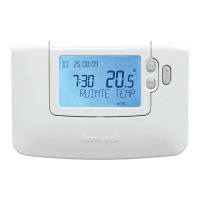
HOLES (10) CODED
PER MANUFACTURER
(J = JOHNSON, P = POWERS,
R = ROBERTSHAW)
TUBING
PILOT HOLE (2)
FOR #6 SELF-TAPPING
SCREW (PROVIDED)
M17414
Fig. 4. Adapter Plate Installation.
4.
To remove thermostat cover, drive screws
clockwise until cover is free. To remove thermostat
from backplate, spread retaining clips (Fig. 4) and
separate.
5.
After removing temporary plug, push tubes onto
thermostat backplate (mainline tube has air
blowing out and must be connected to the M barb
connection on rear of backplate).
6.
Attach backplate to adapter plate with thread-
forming screws provided with thermostat. Do not
over-tighten screws.
7.
Press thermostat onto backplate until it is fully
seated and backplate clips have engaged
(see Fig. 5).
8.
Remove shipping stops (see Fig. 6).
9.
Mount cover (see Thermostat Cover Mounting
section).
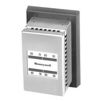
SET
SCREWS
RETAINING
CLIPS
AIR TUBING
CONNECTIONS
(3)
COVER
MOUNTING
M17415
EARS
Fig. 5. Backplate.
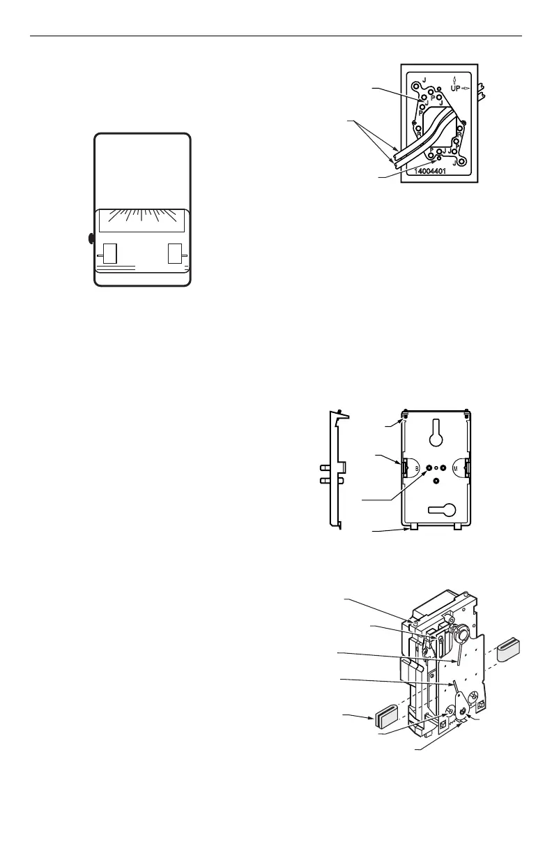
QUICK-MOUNT STAT
SETSCREWS
THROTTLING RANGE
SETTING INDICATOR
C7257
TEMPERATURE
INDICATOR
CALIBRATION SCREW
SETPOINT
LOCK
SCREW
STOPS-TEMPERATURE SETTING
SETPOINT
INDICATOR
SHIPPING STOP (2)
(REMOVE WHEN
INSTALLING)
60
70
80
90
SETPOINT ADJUSTMENT
Fig. 6. TP970 Series Thermostat
with Cover Removed.
3 85-0210EF—1
 Loading...