COMFORTPOINT PROGRAMMABLE LON, VAV/UNITARY CONTROLLERS
7 62-0288—03
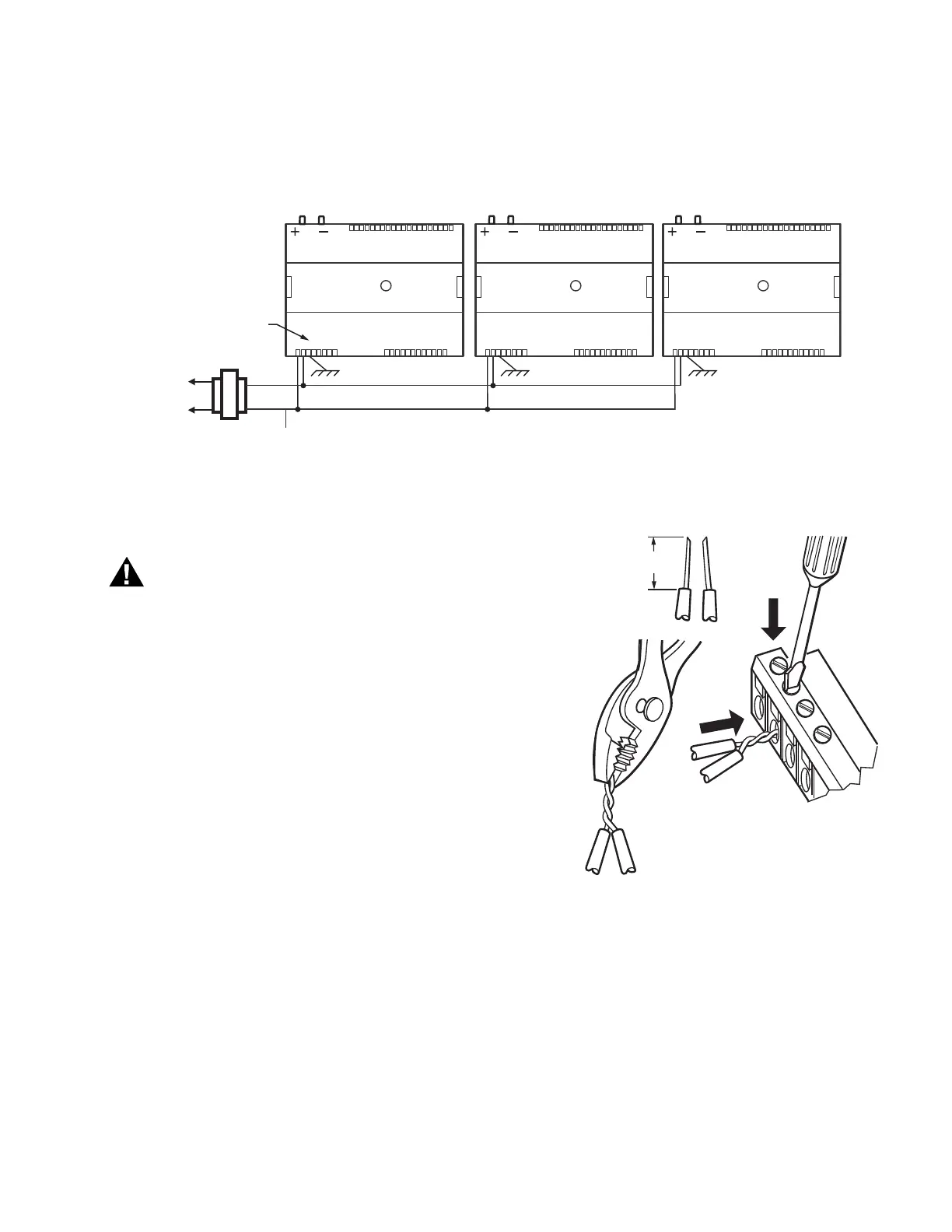
NOTE: Controller configurations are not necessarily limited
to three devices, but the total power draw, including
accessories, cannot exceed 100 VA when powered
by the same transformer (U.S. only). For power
wiring recommendations, see “Wiring” on page 6.
Fig. 12. Power wiring details for two or more controllers per transformer.
Wiring Method
Electrical Shock Hazard.
Can cause severe injury, death or property
damage.
Disconnect power supply before beginning wiring, or
making wiring connections, to prevent electrical shock
or equipment damage.
NOTE: When attaching two or more wires to the same termi-
nal, other than 14 AWG (2.0 sq mm), be sure to twist
them together. Deviation from this rule can result in
improper electrical contact (see Fig. 13).
Each terminal can accommodate the following gauges of wire:
— Single wire: from 22 AWG to 14 AWG solid or stranded
— Multiple wires: up to two 18 AWG stranded, with 1/4 watt
wire-wound resistor
Prepare wiring for the terminal blocks, as follows:
1. Strip 1/2 in. (13 mm) insulation from the conductor.
2. Cut a single wire to 3/16 in. (5 mm). Insert the wire in
the required terminal location and tighten the screw.
3. If two or more wires are being inserted into one terminal
location, twist the wires together a minimum of three
turns before inserting them (see Fig. 13).
4. Cut the twisted end of the wires to 3/16 in. (5 mm)
before inserting them into the terminal and tightening
the screw.
5. Pull on each wire in all terminals to check for good
mechanical connection.
Fig. 13. Attaching two or more wires at terminal blocks.
Controller Replacement (CP-VL0000AS,
CP-VL4022AS, and CP-VL6436AS)
For CP-VL0000AS, CP-VL4022AS, and CP-VL6436AS
controllers, which are hard-wired to an actuator, perform the
following actions to replace the complete assembly (controller
and actuator):
1. Remove all power from the controller.
2. Remove the two air flow pickup connections from the
pressure sensor.
3. Remove the terminal blocks.
4. Remove the old controller and actuator assembly from
its mounting.
M23559A
120/240
VAC
TRANSFORMER
OUTPUT
DEVICE
POWER
ΔP
1
2
3 4 5 6
7 8
1 0 9 2 3 4 5 6 7 8 0 9
1 1 1 1 1 1 1 1 1 2 1
1
2
3 4
5
6
7 8
0
9
2
2 2
2 2
2
2
2 2
3
3
1
2
3 4
5
6
7 8
0
9
3
3
3
3 3
3 3
3 4
COM
24 VAC
ΔP
1
2
3 4 5 6
7 8
1 0 9 2 3 4 5 6 7 8 0 9
1 1 1 1 1 1 1 1 1 2 1
1
2
3 4
5
6
7 8
0
9
2
2 2
2 2
2
2
2 2
3
3
1
2
3 4
5
6
7 8
0
9
3
3
3
3 3
3 3
3 4
EARTH
GROUND (TERMINAL 3)
ΔP
1
2
3 4 5 6
7 8
1 0 9 2 3 4 5 6 7 8 0 9
1 1 1 1 1 1 1 1 1 2 1
1
2
3 4
5
6
7 8
0
9
2
2 2
2 2
2
2
2 2
3
3
1
2
3 4
5
6
7 8
0
9
3
3
3
3 3
3 3
3 4
EARTH
GROUND (TERMINAL 3)
EARTH
GROUND (TERMINAL 3)
CONNECT POWER TO
TERMINALS 1 AND 2
1/2
(13)
STRIP 1/2 IN. (13 MM)
FROM WIRES TO
BE ATTACHED AT
ONE TERMINAL.
1.
2.
TWIST WIRES
TOGETHER WITH
PLIERS (A MINIMUM
OF THREE TURNS).
3. CUT TWISTED END OF WIRES TO 3/16 IN. (5 MM)
BEFORE INSERTING INTO TERMINAL AND
TIGHTENING SCREW. THEN PULL ON EACH
WIRE IN ALL TERMINALS TO CHECK FOR
GOOD MECHANICAL CONNECTION.
M17207

 Loading...