DR4300 Circular Chart Recorder
DR4300 Circular Chart Recorder Product Manual 3/0044
7
TB2
TB1
7
TB2
TB1
-V
+V
24 V Output
Transmitter Power Module
24 Vdc*
* See transmitter’s instruction manual for
power supply/receiver wiring details.
+
–
XMTR
Pen #1
TB2
Pen #2
TB2
–
24 Vdc*
50 mA maximum
+
Main PCA
Pen 1
Main PCA
Pen 2
+
R
–
+
R
–
XMTR
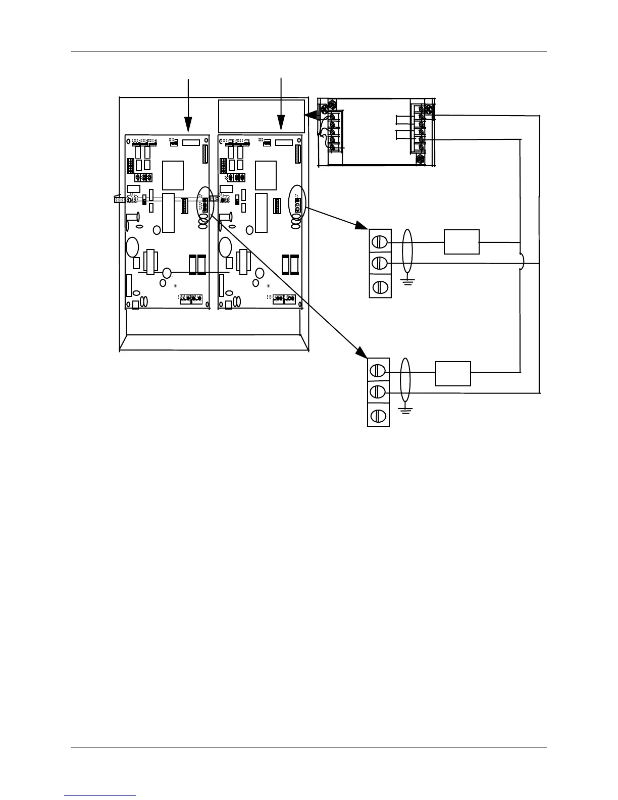
Figure 2-17 Transmitter Power Out Wiring
NOTE: Ensure switches on SW6 are set to their correct positions prior to applying power
to transmitter supply.
For switch settings see Table 3-2 (recorders without display) or Table 4-3 (recorders with display).
 Loading...