EasyManua.ls Logo

Honeywell e528 User Manual

Honeywell e528
15 pages
To Next Page IconTo Next Page
Page #1 background imageLoading...
Page #1 background image
E528 Product Guide
Rev 8.0 12/16/2016 1
E528 Smart Digital Thermostat Product Guide
Table of Contents
Table of Contents .............................................. Page 1
Overview and General Concept ......................... Page 2
Application ......................................................... Page 2
Wireless Communication ................................... Page 4
Installation Requirements .................................. Page 4
Mounting ............................................................ Page 5
Input/Output ....................................................... Page 6
E528.4G New Installation .................................. Page 8
Wiring ................................................................ Page 10
Load Specifications ........................................... Page 13
FCC Information ................................................ Page 13
Technical Specifications .................................... Page 14
Document Revision History ............................... Page 15
Question and Answer IconNeed help?

Do you have a question about the Honeywell e528 and is the answer not in the manual?

Honeywell e528 Specifications

General IconGeneral
BrandHoneywell
Modele528
CategoryThermostat
LanguageEnglish

Summary

Overview and General Concepts

Application

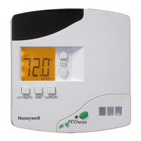
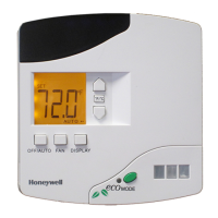
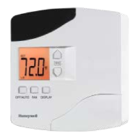
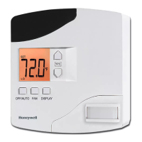
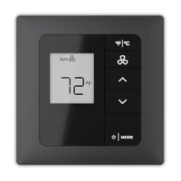
Details the e528 thermostat's basic function, advanced capabilities, and role in hotel energy management systems.

Wireless Communication

Installation Requirements

Guidelines for optimal e528 thermostat placement, considering location and environmental factors for accurate measurements.

PIR Motion Detection Installation

Key considerations for PIR motion detector mounting and view angle to ensure effective guestroom coverage.

Mounting the e528 Thermostat

Input/Output Connections

e528.3G Header Pinout

Details the 10-pin Molex socket and pin assignments for the e528.3G model, used for HVAC unit power, fan, and valve signals.

e528.4G Header Pinout

Details the 10-pin Molex socket and pin assignments for the e528.4G model, including RS485 network connectivity.

E528.4G Installation Procedures

Standalone Installation

Instructions for installing the e528.4G as a standalone unit, with or without a door switch input.

RS485 Networked Installation

Steps for connecting the e528.4G into an RS485 network, with or without a door switch input.

Wiring Guide

Load Specifications

Technical Specifications

Document Revision History

Related product manuals