VOLT FREE CHANNELS
1 - 1 2 - 2
COMMS BUS
+ 4 -
+ 3 -
+ 2 -+ 1 -
DIMMING CHANNELS
N L
MAINS INPUT
VOLT FREE CHANNELS
N2 L2
N1 L1
CH2
ML
CH3CH1
CH4
CH4
CH3
CH1
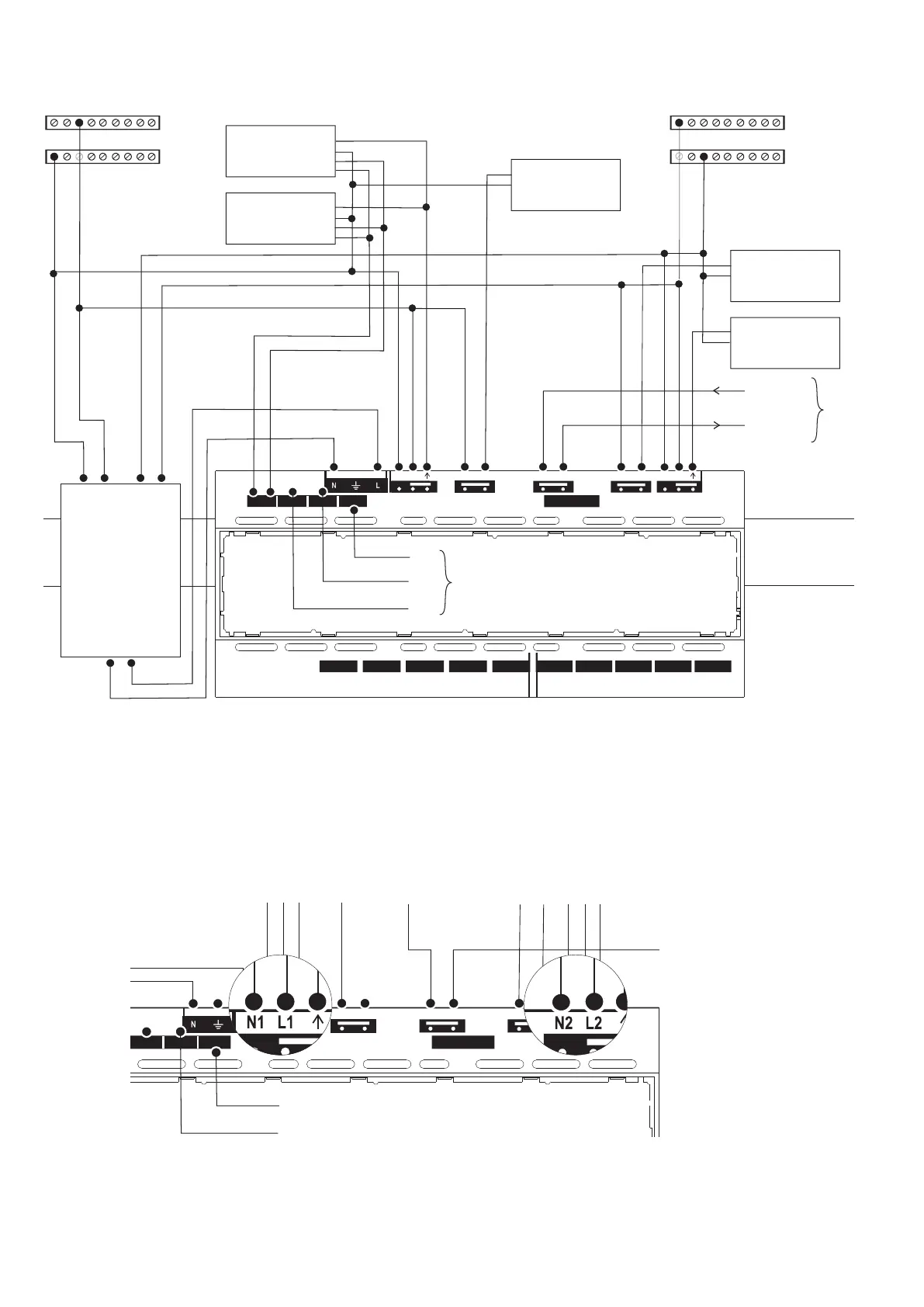
Supply Failure Detection Mode
Channel 1 & Channel 4 are equipped with three-wire pluggable terminals with provision of connecting Neutral and Live from each supply. On detection of supply
failure on Channels 1 or 4, the unit enters into special operating mode. During this mode, the unit controls the output of luminares connected to the channel(s)
fed by the remaining supply according to the settings of Scene 5. During this special operating mode, the unit will continue to respond to switch inputs and
occupancy detection. The unit automatically reverts to normal behaviour once the failed supply has been restored.
Note: Please refer to the Commissioning section for programming the channel output settings of Scene 5.
As shown in the diagram above, two equal supplies may be connected from a single phase or different phases. In order to maintain constant supply to the unit an
external change-over contactor* is required. Line terminals from each of the supplies (N1, L1 and N2, L2) are connected via the change-over contactor. The
Live and Neutral outputs from the contactor are connected to the mains input of the unit. In the case of failure of one of the supplies, the change-over contactor
switches to the alternative supply to ensure continuous supply to the unit. As shown in the diagram above, one or more channels may be wired to run from either
supply.
* Such as Lovato BG series mini-contactor.
Note: Please refer to AN4027 for recommendations on wiring supplies to the change-over contactor and part number.
c) Two Supplies Equally Likely to Drop Out
Ballast
N
L
E
D
D
Ballast
N
L
E
D
D
Ballast
Ballast
Ballast
N
N
N
L
L
L
E
E
E
D
D
D
D
D
D
1
DETECTOR PORTS
2
3
4
5
B COM AB COM AB COM AB COM AB COM A
12
3
4
5
SELV SWITCH INPUTS
VOLT FREE CHANNELS
1 - 1 2 - 2
COMMS BUS
+ 4 -
+ 3 -
+ 2 -+ 1 -
DIMMING CHANNELS
N L
MAINS INPUT
VOLT FREE CHANNELS
N2 L2
N1 L1
CH2
ML
CH3CH1
CH4
DD
Emergency
Luminaire
Maintained
Live
CH4
CH3
CH2
CH1
CH1
CH2
CH3
CH4
L
N
Changeover
Contactor
N
L
N2 L2
L
L1
N1
N
Can be
derived
from
either
supply
SUPPLY 2SUPPLY 1
Earth not
shown for
clarity
Dimming
-4-

 Loading...