EXCEL 50 INSTALLATION INSTRUCTIONS
EN1B-0101GE51 R1105D 10
Inside Cabinet with MMI
The screw terminal blocks and the switch for the bus ter-
mination cannot be accessed after the controller with MMI is
mounted on the DIN rail.
Although the bus terminal socket can still be plugged in and
unplugged, it is easier to do the complete installation before
mounting the controller on the DIN rail:
1. Plug in the application module as shown in Fig. 13.
2. Read the complete chapter "Installation" carefully.
3. Follow the instructions in section "Screw Terminal Block
Installation Procedure".
4. Optional: Connect the C-Bus to the application module
as described in section "C-Bus Connection Procedure"
and/or connect the application module serial port to the
Meter-Bus adapter as described in section “Meter-Bus
Connection Procedure”.
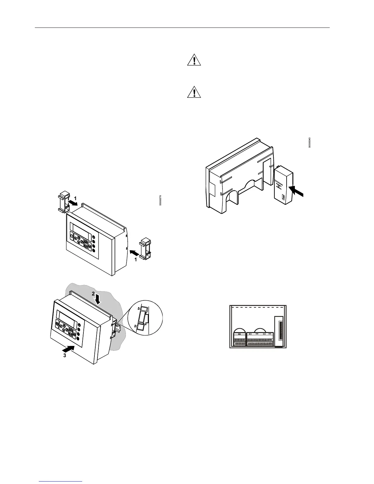
5. Break plastic tabs covering the slots on the controller for
the DIN rail mounting clips using a screwdriver.
6. Attach the DIN rail mounting clips at the housing as
shown in Fig. 13.
7. Mount the controller on the DIN rail.
Fig. 13. Cabinet mounting with MMI
Application Module
CAUTION
Always plug in the application module before
connecting the power supply.
CAUTION
Always disconnect the power supply before
unplugging the application module.
— Plug in the application module until it snaps into the
controller housing.
Fig. 14. Plug-in of application module
NOTE: If the application module has been replaced or
plugged out and in again, please push the reset
button (behind I/O terminals) after power on.
INSTALLATION
Direct wiring of the Excel 50 is performed using screw
terminal blocks. For proper installation, follow these
instructions. Read all of section "Installation" carefully.
BL

 Loading...


