EXCEL 5000™ SYSTEM STYLED CABINET RINGS AND SUBPANELS
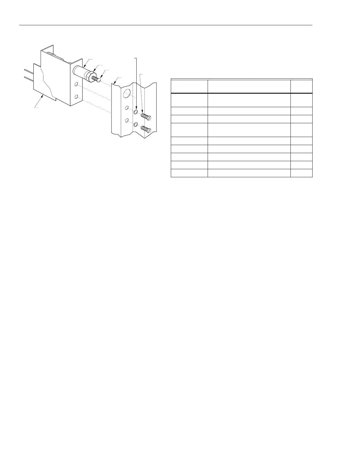
LOCKNUT
PLUNGER
SCREW
RING
LOCK
WASHERS
SCREWS
PLUNGER
TAMPER
SWITCH
C7086
Fig. 9. Tamper Switch location and installation.
WIRING AND PIPING
All wirin
must conform to applicable local codes, ordinances
and re
ulations.
Fi
. 4 and 5 show conduit knockout sizes and locations for
small-sized and full-sized Rin
.
REPLACEMENT PARTS
Table 1 lists replacement parts for the St
led Cabinet Rin
and Subpanel.
Table 1. Replacement Parts List.
Part No. Description
See Fig.
X
14507358-001 Subpanel, Small-Sized Controller
CPU.
1, 3
14507358-002 Subpanel, Small-Sized ACP No. 1. 1, 3
14507358-003 Subpanel, Small-Sized ACP Panel. 1, 3
14507354-001 Subpanel, Full-Sized Controller
CPU.
1, 3
14507354-002 Subpanel, Full-Sized ACP No. 1. 1, 3
14507354-003 Subpanel, Full-Sized ACP. 1, 3
14507305-001
Rin
, Small Sized. 1, 3
14507305-002 Rin
, Full Sized. 1, 3
14505159-001 Tamper Switch. 9
MAINTENANCE PROCEDURES
The e
uipment mounted in this enclosure must be maintained
in accordance with the s
stem documentation and procedures
and practices contained in applicable NFPA and UL
standards. For service, contact
our local Hone
well Home &
Buildin
control office as listed in the phone book or contact a
re
ional office as shown at the end of this document.
95-7487—1 6

 Loading...


