EXCEL 5000™ SYSTEM STYLED CABINET RINGS AND SUBPANELS
NOTE: Mountin
hardware must meet U.S. Government
G.S.A. specification FF-S-325 Group II, T
pe 3,
Class 3.
Other mountin
methods are allowed to meet the construction
methods used in the field, provided the
are at least as stron
as the methods detailed above.
Alternative mountin
methods of e
ual or
reater stren
th are
allowed provided the
also meet or exceed all local code
re
uirements.
Surface Mounting
1.
Use the Rin
as a template and mark and drill four
mountin
holes
see Fi
. 3
.
2.
Use the proper mountin
hardware for wall construction
and secure Rin
to mountin
surface with four 1/4 in.
diameter bolts or screws
see Fi
. 3
.
3.
Install a dirt barrier
scrap cardboard or plastic sheet
on
the front of the Rin
to block construction debris, if
needed.
4.
Continue with the Subpanel Mountin
section.
Semiflush Mounting
1.
Refer to Fi
. 3 for rou
h-in hole dimensions.
NOTE: Rin
mountin
depth in wall
see Fi
. 7
depends on
wall construction and
ob specifications. However,
the Rin
must extend a minimum of 3/4 in.
19 mm
from wall.
2.
Use the proper mountin
hardware for wall construction
and secure Rin
to mountin
surface with four 1/4 in.
diameter bolts or screws
see Fi
. 3
.
3.
Install a dirt barrier scrap cardboard or plastic sheet
on
the front of the Rin
to block construction debris, if
needed.
4.
Continue with the Subpanel Mountin
section.
Subpanel Mounting
After construction is complete, remove the dirt barrier and an
debris on front of Rin
and install Subpanel
see Fi
. 8
.
Tamper Switch (Optional)
1.
Remove the two screws and lock washers from the
Tamper Switch.
2.
Assemble a lock washer on each screw.
3.
Install the Tamper Switch
see Fi
. 9
NOTE: For ease of installation, install the top screw and lock
washer first.
4.
Ti
hten both screws and check for proper switch opera-
tion
plun
er moves freel
.
5.
Loosen lock-nut and ad
ust plun
er screw for proper
Tamper Switch operation.
6.
Hold plun
er screw and ti
hten lock-nut.
7.
Wire the Tamper Switch accordin
to
ob drawin
s.
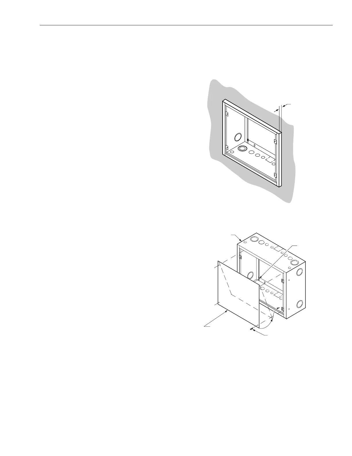
WALL
RING EXTENDS
A MINIMUM OF
3/4 IN. (19 MM)
FROM WALL
C7088
Fig. 7. Semiflush mounted Ring (small sized Ring shown).
FASTENERS
PROVIDED
WITH RING
RING
INSERT BOTTOM OF
SUBPANEL FIRST
NO. 10 x 3/8-IN.
SHEET METAL SCREW
(OBTAIN LOCALLY)
SMALL-SIZED SUBPANEL (4)
FULL-SIZED SUBPANEL (6)
C7085
Fig. 8. Subpanel installation (small-sized Ring shown).
5 95-7487—1

 Loading...


