EXCEL 5000™ SYSTEM STYLED CABINET RINGS AND SUBPANELS
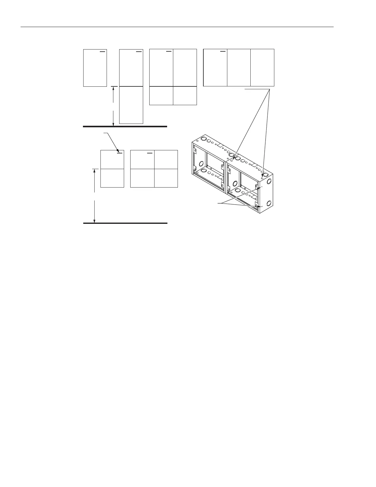
40 (1016)
NAMEPLATE
54 (1372)
USE 1/4-20 x 3/4-IN.
BOLTS, NUTS, AND
5/16 (8) KNOCKOUTS
USE 1/4-20 x 3/4-IN.
BOLTS, 1-1/4-IN.
DIAMETER WASHERS
WITH 1/4-IN. HOLE
(CCT2369 OR EQUAL),
NUTS, AND 1/2 (13)
KNOCKOUTS TO
FASTEN CABINETS
VERTICALLY.
(OBTAIN BOLTS,
WASHERS, AND
NUTS LOCALLY.)
TO FASTEN CABINETS
HORIZONTALLY.
(OBTAIN BOLTS,
WASHERS, AND
NUTS LOCALLY.)
C7084
Fig. 6. Surface, semi-flush Ring arrangements (dimensions in in. (mm)).
General Mounting
— The cabinet/enclosure must be attached to a solid surface
masonr
or concrete slab
or to the wall framin
members.
— The cabinet attachment must be securel
anchored to the
wall and be desi
ned to hold at least four times the wei
ht
of a full-loaded cabinet.
— Enclosure mountin
must be in accordance with all
applicable codes.
— The maximum wei
ht of the enclosure and its contents
must not exceed 50 lbs.
— Unless otherwise noted, the top of the cabinet is positioned
at the top of the drawin
s in this document.
— The cabinet must be mounted in the position shown.
Drywall
To mount:
1.
Use at least four mountin
points and all of the enclo-
sure mountin
holes must be ali
ned over the center of
the studs.
2.
Use a minimum 1/4 in.
6 mm
x 2-1/2 in.
64 mm
la
screw with flat washer and lock washer into center of
stud.
Concrete
To mount:
1.
Establish a minimum of four mountin
points in the con-
crete and ali
n with the cabinet mountin
holes at the
four corners of the enclosure.
2.
Install carbon steel wed
e anchors with 1/4 in. diameter
x 2-1/4 in. lon
57 mm
minimum screw
ITW Ramset/
Red Head Trubolt or e
ual
, per the manufacturer’s
instructions, to a depth of at least 1-15/16 in.
49 mm
.
3.
Bolt the four corners of the enclosure to the wall usin
this hardware and a 1/4 in.
6 mm
steel split lock
washer.
NOTE: Mountin
hardware must meet U.S. Government
G.S.A. specification FF-S-325 Group II, T
pe 4,
Class 1.
Masonry
To mount:
1.
Establish a minimum of four mountin
points in the
masonr
and ali
n with the cabinet mountin
holes at
the four corners of the enclosure.
2.
Install carbon steel sleeve anchors desi
ned to accept
1/4 in. diameter
6 mm
x 1-1/2 in. lon
38 mm
screws
ITW Rasmet/Red Head D
nablot or e
ual
, per the
manufacturer’s instructions, to a depth of at least 1-1/4
in.
32 mm
3.
Bolt the four corners of the enclosure to the wall usin
this hardware and a 1/4 in.
6 mm
steel split lock
washer.
95-7487—1 4

 Loading...


