H1008A,D AUTOMATIC HUMIDITY CONTROL
68-0207—3
3
Location and Mounting
H1008A,D Automatic Humidity Control
IMPORTANT
Do not install H1008 on supply air. Temperatures in
excess of 120
°
F cause the control to go into error
mode. If mounting near an elbow area, keep the
control 6 in. (152 mm) upstream from the elbow so
that the humidity and temperature sensor is exposed
to the normal airflow (Fig. 2).
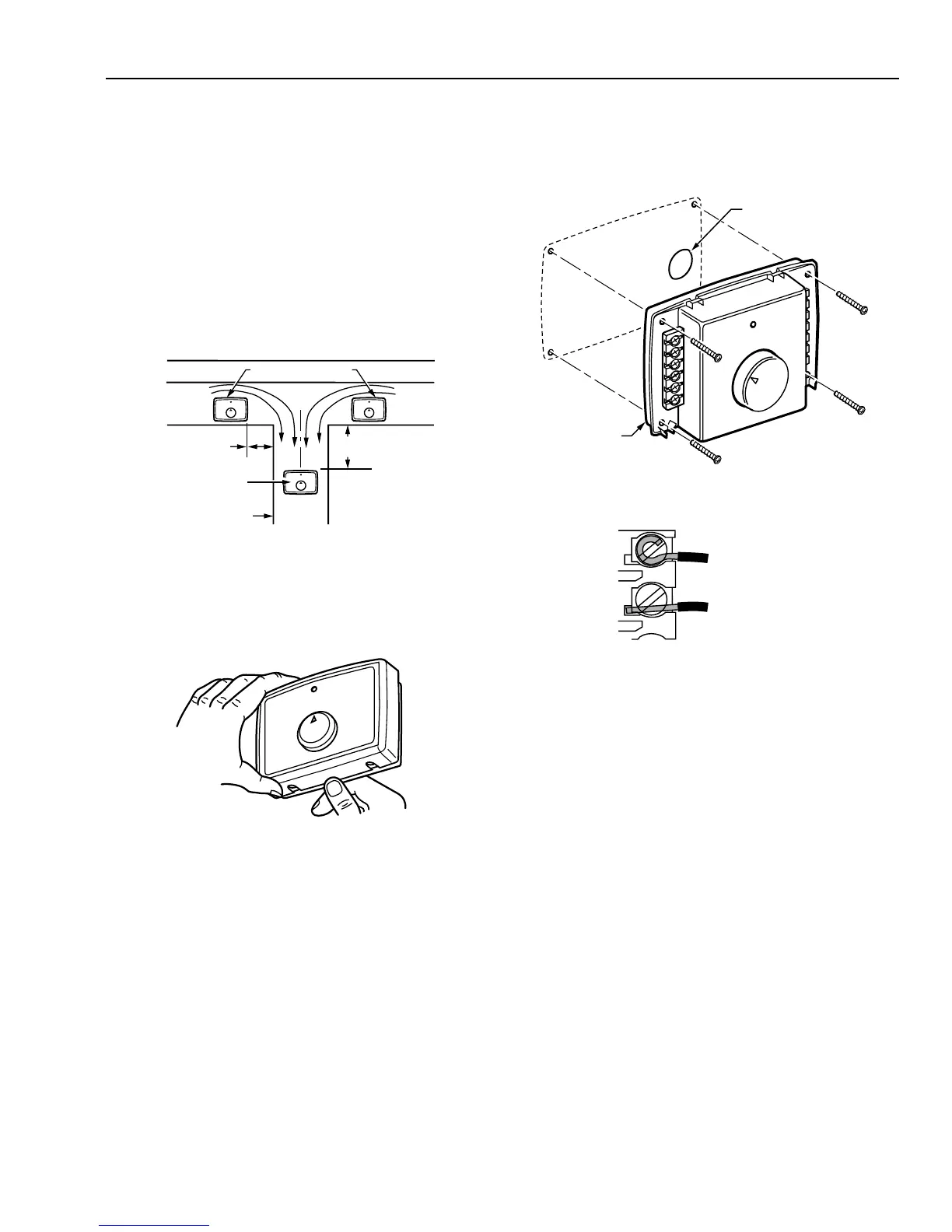
Locate the control at least 12 in. (305 mm) upstream from the
humidifier (or dehumidifion/ventilator supply air) in the return air
duct where it can be exposed to the air stream of the return air.
See Fig. 2.
Fig. 2. Select duct location for control.
Use the following procedure to mount the H1008A,D in the
return air duct:
1. Remove the cover by placing your thumb in the bottom
notch between the cover and the base and pulling out
and up. See Fig. 3.
ALTERNATE LOCATION
RETURN
AIR
RETURN
AIR
6 in. (152 mm)
MINIMUM
15 in. (381 mm)
MINIMUM
BEST
LOCATION
RETURN AIR DUCT
M12822
M12828
Fig. 3. Remove cover from base.
2. Drill 3/4 in. (19 mm) circular opening for the projection on
the back of the base. See Fig. 4. Place the device on the
duct and mark the mounting holes, or screw in the self-
tapping screws.
NOTE: Be sure the sheet metal surface is flat after
drilling and cutting holes.
3. Mount the base on the duct using the four mounting
screws provided. Tighten the screws firmly so the space
between the base and the duct is seated. See Fig. 4.
M12827
FOR WRAPAROUND
INSERTION STRIP
7/16 IN. (11 MM).
FOR STRAIGHT
INSERTION STRIP
5/16 IN. (8 MM).
4. Run a low voltage wire from the humidifier and
equipment to the control terminals. See Fig. 6-11. Use
either straight in or wraparound wiring connections. See
Fig. 5.
5. Snap the cover onto the base.
Fig. 4. Mount control on return air duct.
Fig. 5. Proper wiring technique.
C7089H Outdoor Temperature Sensor
NOTE: The C7089H Outdoor Temperature Sensor is required
only when using the H1008A control with heat pump,
multi-stage equipment or multi-zone applictions.
Mount the sensor (purchased separately):
— out of direct sunlight on the North side of the house.
— at least three feet from dryer vents or other vents.
— above the expected snow line where ice and debris cannot
cover it.
Use the following procedure for mounting:
1. Place the sensor in the clamp provided.
2. Insert the screw provided through the holes in the clamp
and fasten the sensor in place.
 Loading...