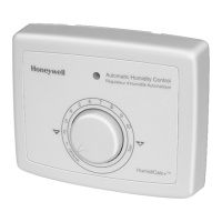
H1008A,D AUTOMATIC HUMIDITY CONTROL
68-0207—3
4
WIRING
CAUTION
Voltage Hazard.
Power supply can cause electrical shock and injury.
Disconnect power supply before installation or
servicing.
All wiring must comply with applicable local codes,
ordinances and regulations.
IMPORTANT
Use 18- to 22-gauge insulated wire for proper wiring.
Stranded-tinned wire is recommeded.
To wire the Automatic Humidity Control:
IMPORTANT
When installing a steam-powered humidifier, be sure
to cut the factory-installed steam jumper wire for
proper operation.
1. Connect 24 Vac power to the 24 Vac HOT and COM
terminals on the H1008A,D.
2. Connect the humidifier to the two HUM terminals on the
H1008A,D as shown in Fig. 6 through 11.
3. In furnace systems with two transformers, connect CG
to the cooling system transformer common and connect
CW to the heating transformer common. Be sure G and
W connect to the R terminals of both transformers. (If
only one transformer is used, leave the jumper on CG
and CW.) See Fig. 6.
4. To Wire the C7089H Outdoor Temperature Sensor, wire
the sensor to the two OUT terminals on the H1008A,D.
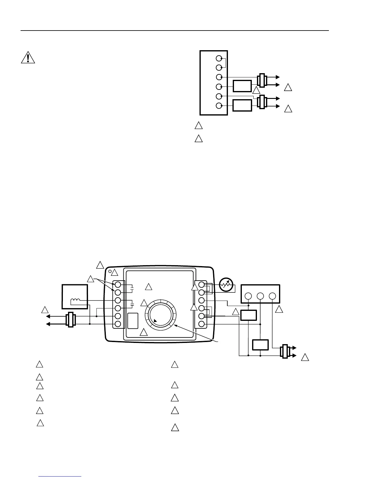
Fig. 7. Wiring for flow-through by-pass humidifiers.
DEHUM
24 VAC
BLACK
WHITE
DEHUM
HUM
HUM
HOT
COM
OUT
OUT
G
CG
CW
W
OFF TEST
24 VAC
SOLENOID
FROST
FACTOR
SETPOINT
DIAL
OPTIONAL
OUTDOOR
AIR SENSOR
1
2
3
4
7
8
6
6
4
3
AUTOMATIC HUMIDITY CONTROL
M13296
L1
(HOT)
L2
1
POWER SUPPLY. PROVIDE DISCONNECT MEANS AND OVERLOAD
PROTECTION AS REQUIRED.
24V WIRING.
TO PROVIDE HUMIDITY IN FAN MODE, CONNECT G AND CG
TERMINALS TO FAN RELAY.
IN TWO TRANSFORMER SYSTEMS, REMOVE CW/CG FACTORY
INSTALLED JUMPER.
IF USING OUTDOOR TEMPERATURE SENSOR, REMOVE FACTORY
INSTALLED JUMPER.
ISOLATED RELAY CONTACTS.
5
ROOM THERMOSTAT
7
L1
(HOT)
L2
1
R
W
G
FAN
RELAY
HEAT
RELAY
FURNACE
TRANSFORMER
10
9
HEAT ONLY APPLICATION SHOWN. SIMILAR WIRING REQUIRED IN HEAT
AND COOL SYSTEM WITH ONE OR TWO TRANSFORMERS. WHEN HEAT
AND FAN OPERATE SIMULTANEOUSLY WITH ONE RELAY, JUMP W TO G
AND JUMP CG TO CW.
POWER SHOULD BE APPLIED TO THIS CONTROL AT ALL TIMES. DO NOT
USE FAN BOARD HUMIDISTAT CONTACTS OR CURRENT SENSING RELAY.
CUT JUMPER FOR DEHUMIDIFIER APPLICATION. (DO NOT CUT FOR
VENTILATION SYSTEM.)
DEHUM TERMINALS SWITCH LOW VOLTAGE DEHUMIDIFIERS, HEAT/ENERGY
RECOVERY UNITS OR EXTERNAL CONTACTORS THAT SWITCH HIGH
VOLTAGE DEHUMIDIFIERS.
JUMPER AND DEHUM TERMINALS NOT PRESENT ON H1008A MODEL.
8
BLACK
9
10
5
6
FLOW
THROUGH
BYPASS
HUMIDIFIER
11
11
G
CG
CW
W
OUT
OUT
HEATING
TRANSFORMER
POWER SUPPLY. PROVIDE DISCONNECT MEANS AND
OVERLOAD PROTECTION AS REQUIRED.
IN SINGLE TRANSFORMER SYSTEMS, JUMPER CG AND CW.
2
1
M13307
120V
COOLING
TRANSFORMER
L1
(HOT)
L2
1
120V
L1
(HOT)
L2
1
2
H1008 AUTOMATIC
HUMIDITY CONTROL
HEATING
RELAY
FAN
RELAY
Fig. 6. Wiring for two-transformer system.
IMPORTANT
For proper wiring, use 18- to 22-gauge wire. Stranded-
tinned wire with a maximum length of 300 ft. (91m) is
recommended.
NOTE: Connect the humidistat to the furnace for two
reasons:
• The control can determine the outdoor
temperature.
• The control knows when the furnace blower is
operating, eliminating the need for current
sensing relays.
 Loading...