HLS PS25 & HLS PS50 User Manual
MN-DT-1305I_B 10
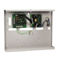
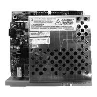
2.4 Control Unit Connections:
The following
4
connectors are placed at the top of the Control Unit:
FAULT
(C) Fault Relay Common
FAULT
(NC) Normally Closed Contact
FAULT
(NO) Normally Open Contact
The faul t rel ay may be li nked to an analogue
input modu le to report any fault t o a third
equipment li ke a FACP ( Fire Alarm Control
Panel).
IN ALARM
(+)
IN ALARM
(-)
Alarm input to d isable, momen tarily, t he battery c harger and be able to supp ly 300 -
600mA from ba ttery loa d to the ou tputs. Fo r th is, i t is necessa ry to l ink both IN
ALARM terminals by means of a jumper or short-circuit.
When this input is activated, the control unit will have an extra current of battery load
0.3 A or 0.6 A, depending on the DIP SW2 for outputs. Thus, if the power supply is in
Overload (Imax) sta te, the indication will disappear by ac tivating this input, p rovided
that the excess current is the current which is supplying batteries.
PSO1
Output 1 (+)
PSO1
Output 1 (-)
PSO2
Output 2 (+)
PSO2
Output 2 (-)

 Loading...

