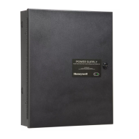
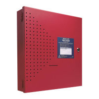
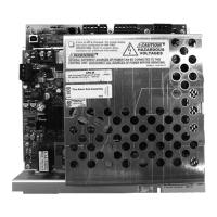
Do you have a question about the Honeywell HPF-PS6B and is the answer not in the manual?
Details features like Default/Retrofit modes, cabinet, power-limited outputs, input/output configurations, and synch.
Explains various uses like remote power supply, NAC extenders, and door holder circuits.
Step-by-step guide for initial configuration, installation, programming, and power-up.
Instructions and diagram for physically mounting the backbox to a wall.
Details standard Class B wiring and the use of the ZNAC-PS module for Class A wiring.
Guidelines for separating power-limited and non-power-limited wiring according to NEC standards.
Lists programming features permitted by UL864/UL2572 and their allowed settings.
Details the functions of S1 DIP switches for global options like debounce, charger, and operating mode.
Describes Default, Retrofit, and temporary modes like configuration change and trouble history display.
Details DIP switch settings (S2-S8) for controlling individual output circuits' functions.
Configuring outputs for Master or Slave synchronization for strobes and notification appliances.
How input circuits monitor troubles like open, short, and power-limiting conditions in Default/Retrofit modes.
Using the Form-C trouble relay at TB1 for monitoring various power supply faults.
Using the Form-C AC trouble relay at TB2 for reporting AC fail conditions with optional delays.
Step-by-step guide to calculate secondary current loads for non-alarm and alarm conditions.
| Brand | Honeywell |
|---|---|
| Model | HPF-PS6B |
| Category | Power Supply |
| Language | English |
