18 HPF-PS Series Instruction Manual — P/N LS10227-003HP-E:C 2/2/2022
Installation Connecting to an External Charger
3. Use only devices from the same manufacturer in each zone or field of view.
4. In this example, the output is mapped to Input#1 in Master Configuration, but it can programmed to another input using the DIP
switches.
5. For NFPA 72 compliance, notification appliances cannot be installed on the FACP control circuit connecting to the HPF-PS input
circuits.
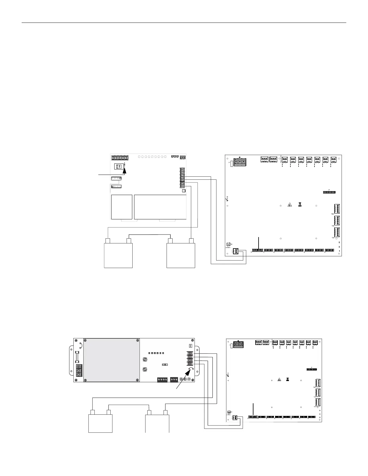
2.7 Connecting to an External Charger
The HPF-PS Power Supply can be connected to an external charger to charge systems requiring over 33AH batteries. Ensure all power has
been disconnected before wiring. Observe polarity when making connections. Wiring must be in conduit within 20 feet (6.096m) in the same
room.
2.7.1 CHG-120
1. Set S1 position 4 on the HPF-PS Power Supply to the OFF position to disable the onboard battery charger.
2. Connect the battery cables between TB15 (+ and –) on the HPF-PS and the CHG-120 charger output circuit (TB2: Out 1+ and Out 1–)
as shown in Figure 2.9. Be certain to observe polarity.
3. Connect the batteries to the charger.
4. Connect the battery interconnect cable only after AC power is applied and batteries are connected. Refer to the CHG-120 Manual for
more information.
5. Cut and remove Jumper R104 on the CHG-120 to disable ground fault supervision.
2.7.2 CHG-75
1. Set S1 position 4 on the HPF-PS Power Supply to the OFF position to disable the onboard battery charger.
2. Connect the battery cables between TB15 (+ and –) on the HPF-PS and the CHG-75 charger output circuit (TB2: Out+ and Out–) as
shown in Figure 2.10. Be certain to observe polarity.
3. Connect the batteries to the charger.
4. Connect the battery interconnect cable only after AC power is applied and batteries are connected. Refer to the CHG-75 Manual for
more information.
5. Cut and remove Jumper JP2 on the CHG-75 to disable ground fault detection.
–
+
–
+
TB1
TB2
–
+
–
+
–
+
NO NC CNONC C
TB4
TB15
T
B
2
T
B
1
A- B+ B- A+ A- B+ B- A+ A- B+ B- A+
R104
TB2
CHG-120
Charger
PS Series Power Supply
Set S1 position 4 to
the OFF position to
disable charger
Battery interconnect cable
12V battery12V battery
Figure 2.9 Connecting the Power Supply to a CHG-120 Charger
Note: If batteries are
disconnected at the
CHG-120 terminals,
battery supervision will
be managed by the
CHG-120.
Cut jumper R104
-
+
-
+
JP1
JP2
SW1
TB3
TB4
TB2
TENS
ONES
CUT FOR
240VAC
ADDRESS
ON OFF
AM-1
F1
J4
J1 J2
J3
TB1
HOT
OUT
+
BAT
+
OUT
-
BAT
-
EARTH
NEUT
A- B- A+ B+
NC NO C
0
4
3
9
2
6
1
5
7
8
12
13
15
14
10
11
0
4
3
9
2
6
1
5
7
8
12
13
15
14
10
11
NO NC CNONC C
TB4
TB15
T
B
2
T
B
1
T
B
O
U
T
1
3
6
T
B
O
U
T
1
2
5
T
B
O
U
T
1
1
4
T
B
O
U
T
1
0
3
T
B
O
U
T
9
2
T
B
O
U
T
8
1
A- B+ B- A+A- B+ B- A+
A- B+ B- A+
TB2
CHG-75
Charger
PS Series Power Supply
Set S1 position 4 to
the OFF position to
disable charger
Battery interconnect cable
12V
battery
12V
battery
Figure 2.10 Connecting the Power Supply to a CHG-75 Charger
+
-
+
-
-
+
Cut Jumper JP2
 Loading...


