HPF-PS Series Instruction Manual — P/N LS10227-003HP-E:C 2/2/2022 23
Section 3: Programming Options
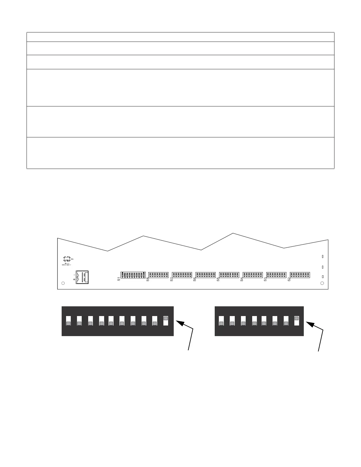
This section describes the programming options available via DIP switch settings. The HPF-PS can be field programmed using DIP switches
S1-S8 which are located at the bottom of the circuit board. S1 controls the global options of the power supply and S2-S8 control the functions
of each output circuit, respectively. Refer to the following illustration for switch locations and DIP switch placement in the ON and OFF
positions.
Important: Activate output DIP switch changes by setting S1 positions 9 and 10 appropriately. Refer to Table 3.8 on page 27 for DIP Switch
programming settings.
NOTICE TO USERS, INSTALLERS, AUTHORITIES HAVING JURISDICTION AND OTHER INVOLVED PARTIES
This product incorporates field-programmable software. In order for the product to comply with the requirements in the Standard for Control Units and
Accessories for Fire Alarm Systems, UL 864, certain programming features or options must be limited to specific values or not used at all as indicated below:
Program feature or option
Permitted in
UL864 / UL2572? (Y/N)
Possible settings
Settings permitted in
UL 864 / UL2572
Door Holder Dropout Delay Y Refer to “AC Loss Door Holder Dropout Timer” on
page 25.
• Does not drop
• 15 seconds
• 5 minutes
• 60 seconds
• Does not drop
• 15 seconds
• 60 seconds
• 5 minutes
AC Loss Delay Timer Y Refer to “AC Fail Indication Delay” on page 26.
• 30 hours
• 12 hours
• 2 hours
• none
• 2 hours
1
•none
1 A two hour delay is only permitted on an addressable FACP.
Operating Mode Y Refer to “Operating Modes” on page 26.
• Retrofit Mode
• Change Output Circuit Configurations
• Display Trouble History
• Default Mode
• Default Mode
2
2 For site compliance to UL864 10th Edition, all power supplies must be configured for Default Mode.
Table 3.1 Agency-Permitted Programming Settings
ON
1 2 3 4 5 6 7 8 9 10
ON
1 2 3 4 5 6 7 8
TB15
Switches 1 through 7 shown
in OFF (Open) position
Switch 8 shown in
ON (Closed) position
Figure 3.1 Field Programming DIP Switches
Switch 10 shown in
ON (Closed) position
Switches 1 through 9 shown
in OFF (Open) position
S1
S2-S8
 Loading...


