22 HPF-PS Series Instruction Manual — P/N LS10227-003HP-E:C 2/2/2022
Installation Ground Fault Detection
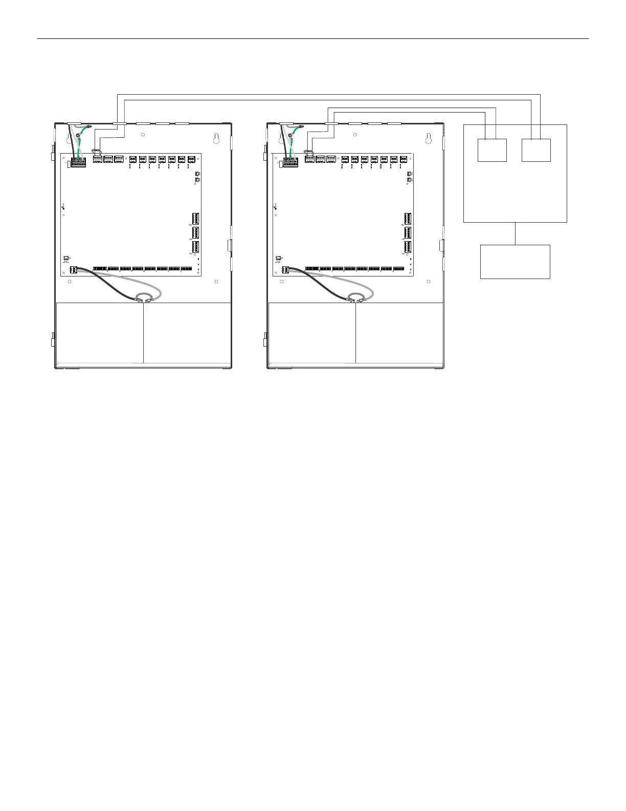
3. Conventional FACP: The FACP must be programmed to turn on the common trouble LED, trouble tone, and a separate yellow
annunciator point when the input connected to the HPF-PS ground fault relay is initiated. Use one input per HPF-PS power supply.
NO NC CNONC C
TB4
TB15
NO NC C
T
B
3
T
B
2
T
B
1
T
B
1
3
T
B
1
2
T
B
1
1
T
B
1
0
T
B
9
T
B
8
NAC1
AUX1
NAC2
AUX2
NO NC CNONC C
TB4
TB15
NO NC C
T
B
3
T
B
2
T
B
1
T
B
1
3
T
B
1
2
T
B
1
1
T
B
1
0
T
B
9
T
B
8
UL 864-listed
conventional
control panel
UL 864-listed
annunciator
Input 1
Figure 2.16 Ground Fault Detection Option 3 - Conventional FACP
Maintain 0.25” spacing
between power-limited and
non-power-limited wiring.
Input 2
 Loading...


