10 HPF-PS Series Instruction Manual — P/N LS10227-003HP-E:C 2/2/2022
System Overview Switch SW1 - Ground Fault Detection
Value of the resistance in between any circuit terminal to Earth, which will cause the Ground Fault detection, depends on the ELR chosen for
inputs and output circuits. This resistance will vary from 9.9K down to 0 Ohm.
Table 1.2 lists the open/short trip values and restoral values in standby for the NAC circuits on the FACP.
1.5 Switch SW1 - Ground Fault Detection
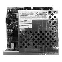
The Ground Fault Detection circuit monitors for ground faults. Switch SW1 is located on the lower left section of the power supply circuit
board. Sliding SW1 to the left will disable ground fault detection by the power supply. This should only be done if ground faults are being
monitored by an FACP connected to the HPF-PS power supply or in a cascading application as shown in Section 2.8.1 on page 19.
Circuit Fault Trip Resistance (in ohms) Restore Value
NAC 1-5/7 Short 1.6K or lower 1.7K or higher
NAC 1-5/7 Open 55K or higher 33K or lower
ZNAC-PS 1-5/7 Short 1.6K or lower 1.7K or higher
ZNAC-PS 1-5/7 Open 45K or higher 21K or lower
Table 1.2 NAC Open/Short Trip Values

 Loading...
