Do you have a question about the Honeywell HPF24S8 and is the answer not in the manual?
Ensures proper system operation after programming or software changes.
Recommends installation environment for optimal system performance and component life.
Guidelines for safely handling static-sensitive components to prevent damage.
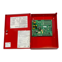
Provides general overview of HPF24S power supply features and capabilities.
Lists key features of the HPF24S power supply, including cabinet, outputs, and compatibility.
Step-by-step guide for configuring, installing, programming, and wiring the power supply.
Explains jumper settings for ground fault detection and input selection, and LED indicators.
Details electrical specifications for AC power, input/output circuits, and relays.
Instructions for mounting the power supply backbox, including grounding strap connection.
Details wiring configurations for Notification Appliance Circuits (NACs), including Style Y and Z.
Instructions for mounting addressable control, relay, or monitor modules within the cabinet.
Explains cabinet wiring separation for power-limited and nonpower-limited circuits.
Describes programming features using DIP switch SW1 and their ON/OFF positions.
Configures strobe synchronization type for various manufacturers' devices.
Sets the power supply to act as a master or slave for strobe synchronization.
Configures delay for AC fail reporting and alters Aux. Trouble Relay response.
Determines how input control circuits activate output circuits and control auxiliary power.
Enables or disables the internal battery charger for external charger use.
Configures Output Circuit #4 for door closer function instead of NAC.
Explains how the FACP supervises the wiring to the HPF24S using an End-of-Line Resistor.
Details how the FACP detects HPF24S power supply faults via NAC open circuit conditions.
Monitors trouble conditions via a fail-safe Form-C aux. trouble relay.
Delays AC loss reporting to prevent false alarms during power stabilization.
Application using master sync outputs and selective silence with one input.
Application controlling three NACs and one door holder with a single input.
Configures synchronized and nonsynchronized outputs for temporal signaling.
Provides filtered, resettable or nonresettable power for various devices.
Connects HPF24S as a slave unit to a master FACP for synchronized output.
Connects HPF24S as a master to an FACP NAC for synchronization.
Requirements for Canadian applications per ULC, including NAC extender use and ground fault monitoring.
Determines the required AC branch circuit current for system operation.
Calculates non-fire and fire alarm current loads for system and secondary power.
Calculates total standby and alarm load in ampere hours (AH) to determine battery size.
Details NFPA requirements for standby and alarm times for fire alarm systems.
Guidance on selecting and locating batteries, including cabinet capacity.
Lists compatible System Sensor, Gentex, and Cooper-Wheelock devices.
Lists System Sensor 24VDC models compatible with the HPF24S.
Details System Sensor SpectrAlert Advance device models.
Lists Gentex 24VDC models compatible with the HPF24S.
Lists Cooper-Wheelock 24VDC models compatible with the HPF24S.
Lists compatible notification appliances for Canadian applications.
| Input Voltage | 100-240 VAC |
|---|---|
| Output Voltage | 24VDC |
| Output Current | 8A |
| Power | 192W |
| Protection | Overload, Overvoltage, Short Circuit |
| Frequency | 60Hz |